Overview
I joined the Schulich Space Rover Team club at the start of my third year in university. The Schulich Space Rover Team is a multidisciplinary club focused on building an imitation Mars rover to compete at the Canadian International Rover Challenge hosted in the region of Alberta’s badlands during the month of August each year. I joined the mechanical subdivision, and furthermore, the chassis/drivetrain sub-team. I was quickly promoted from general member to junior lead and took part in managerial meetings with the the other team leads on a weekly basis. Near the end of the season I ran for team president, but didn’t win the election.
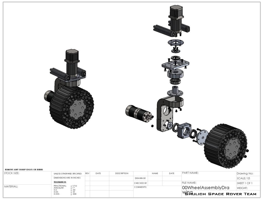
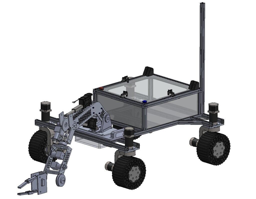
Shown below are my contributions to the team. On the left is the original design the team had going into the 2024-2025 season, and on the right is what I newly designed and built in time for competition that year.
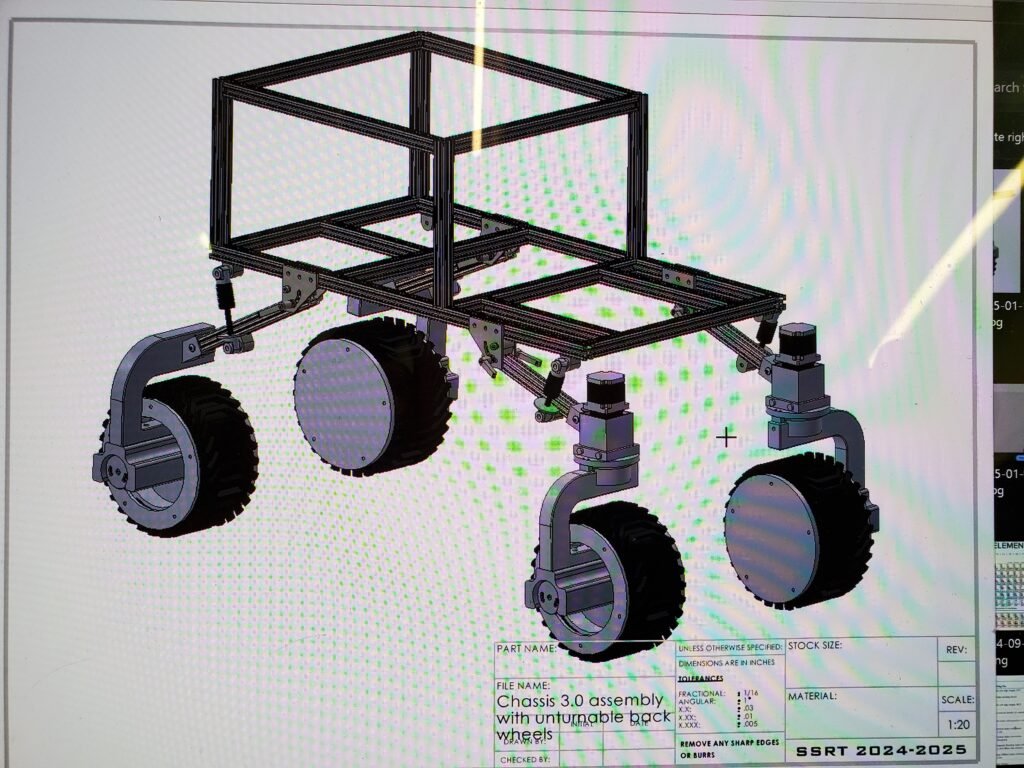
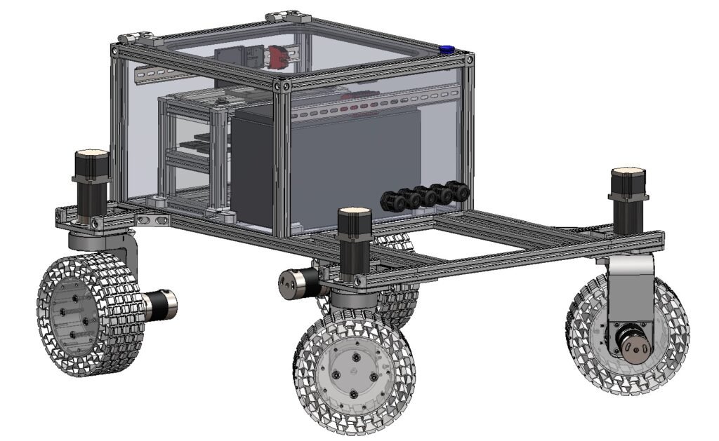
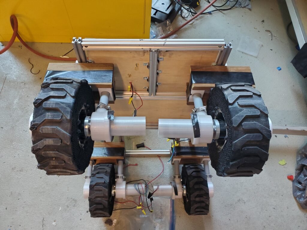
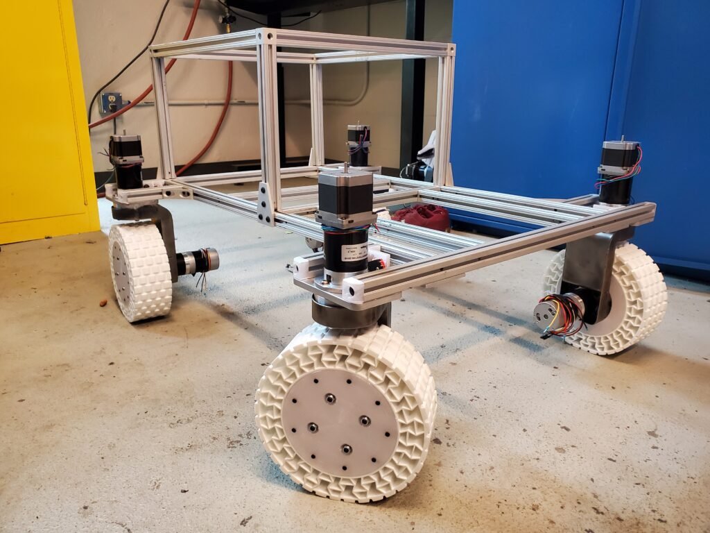
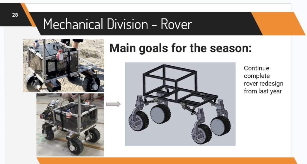
Four-Wheel Independent Steering and Drive + 3D Printed Tires
This was my main goal for the season. The team had previously tried to generate a design for this concept, however it was never fully implemented. This new design took me 8 months to create, and an estimated 150+ hours. Sure, I sacraficed some grades for it, but I was determined to create something that’d work.
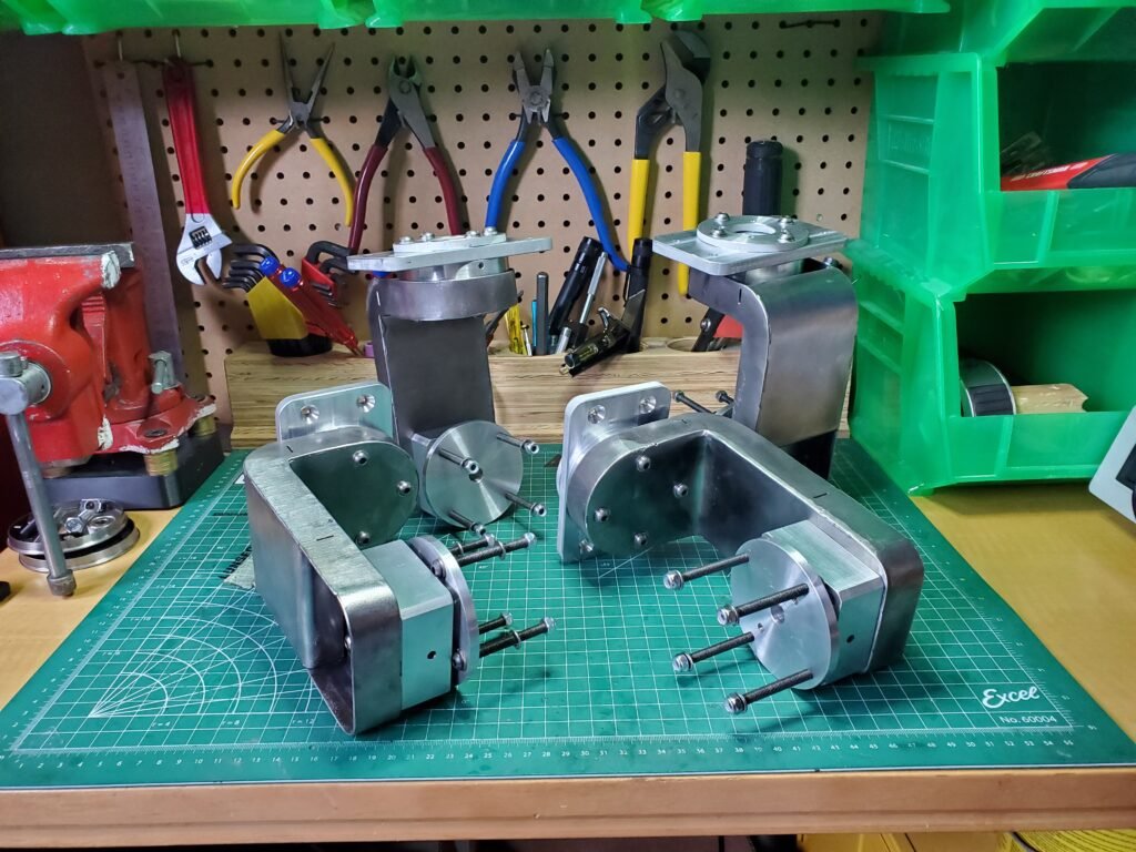
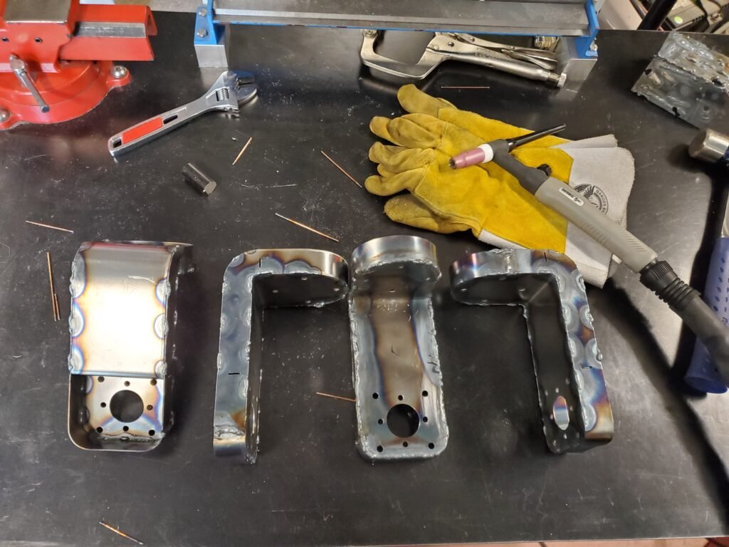
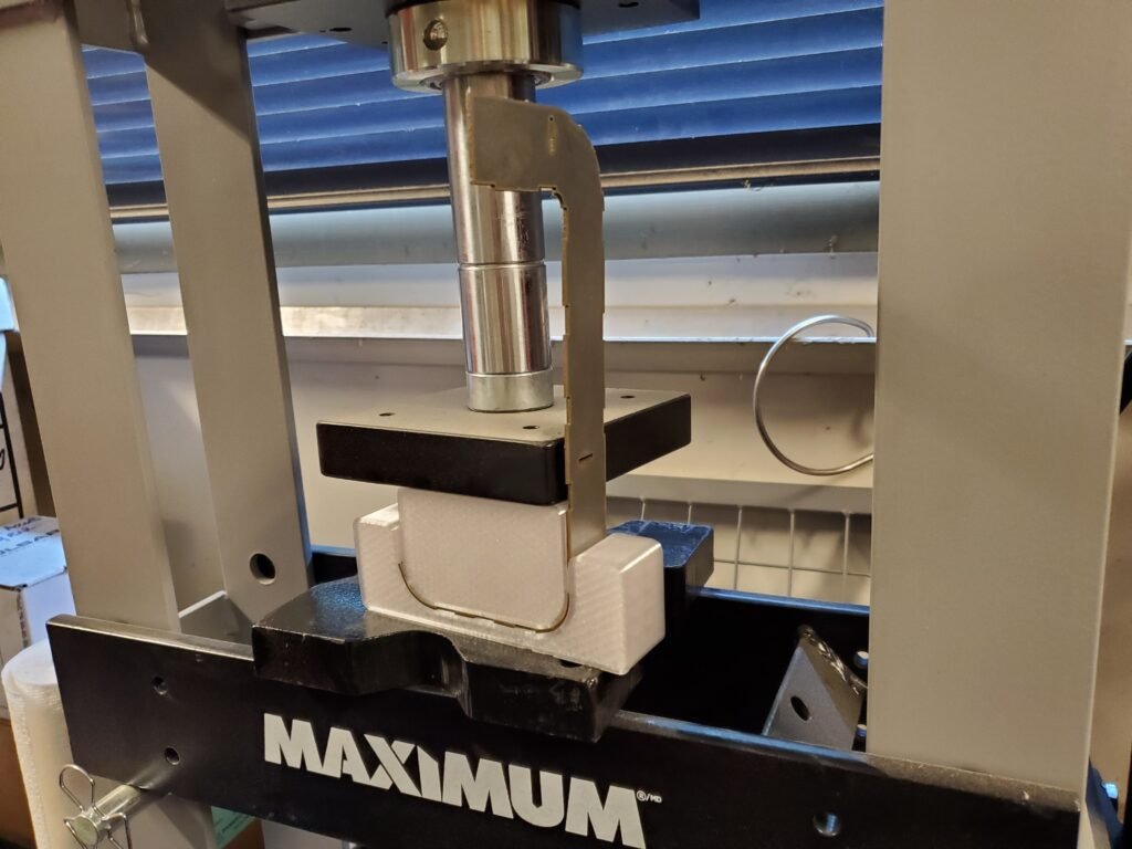
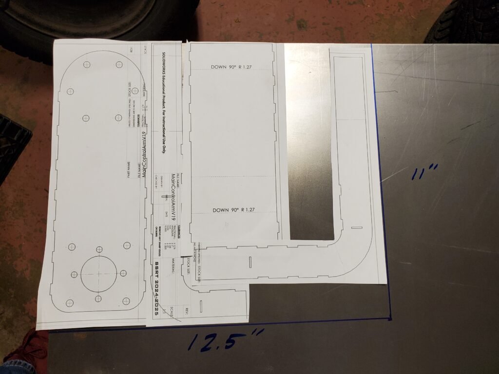
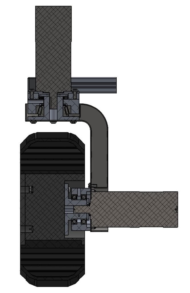
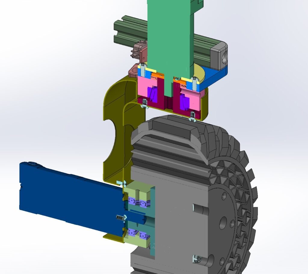
A lot of time was spend iterating the main control arm that connected the steering axis to the drive axis, perpendicularly. Oddly enough, everyone seems to think that part is solid (as opposed to hollow) when they first see it in person! However, it is a bent sheet metal part, with 4 joining parts seam welded together. I made it this way for manufacturability. I didn’t want to create some complicated 5-axis CNC machined part, because I had barely become familiar with the convectional milling machine at the time of designing.
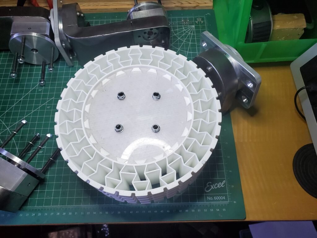
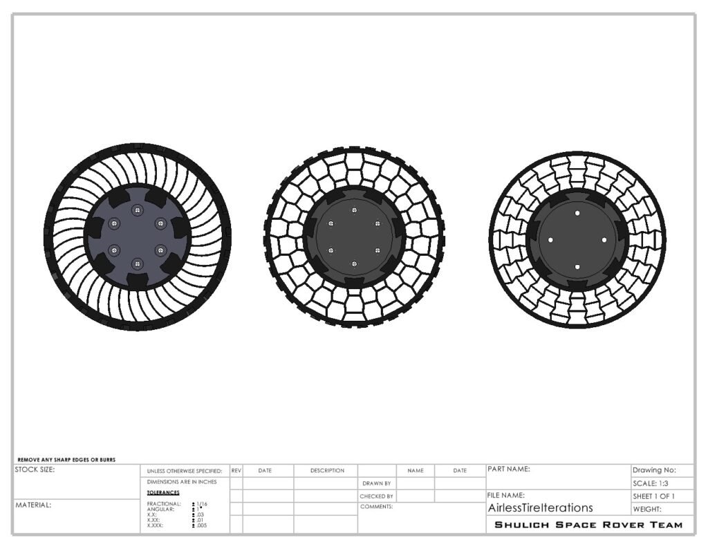
A lot of time was also spent iterating over the wheel’s infill pattern, as I wanted to design this in Solidworks and extrude as a sketch instead of relying on 3D printer slicer infill settings. I used my university library to research some designs and found some ‘auxetic’ infill designs (2-dimensionsional geometry having a negative poisson ratio) with high energy-absorption characteristics since I had to rely on the 3D printed wheels to act as suspension, but also transmit torque.
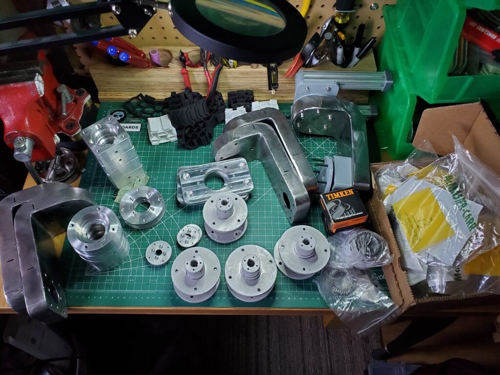
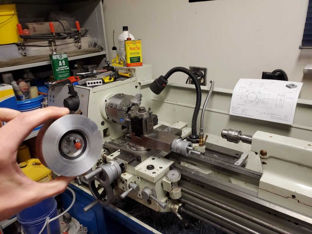
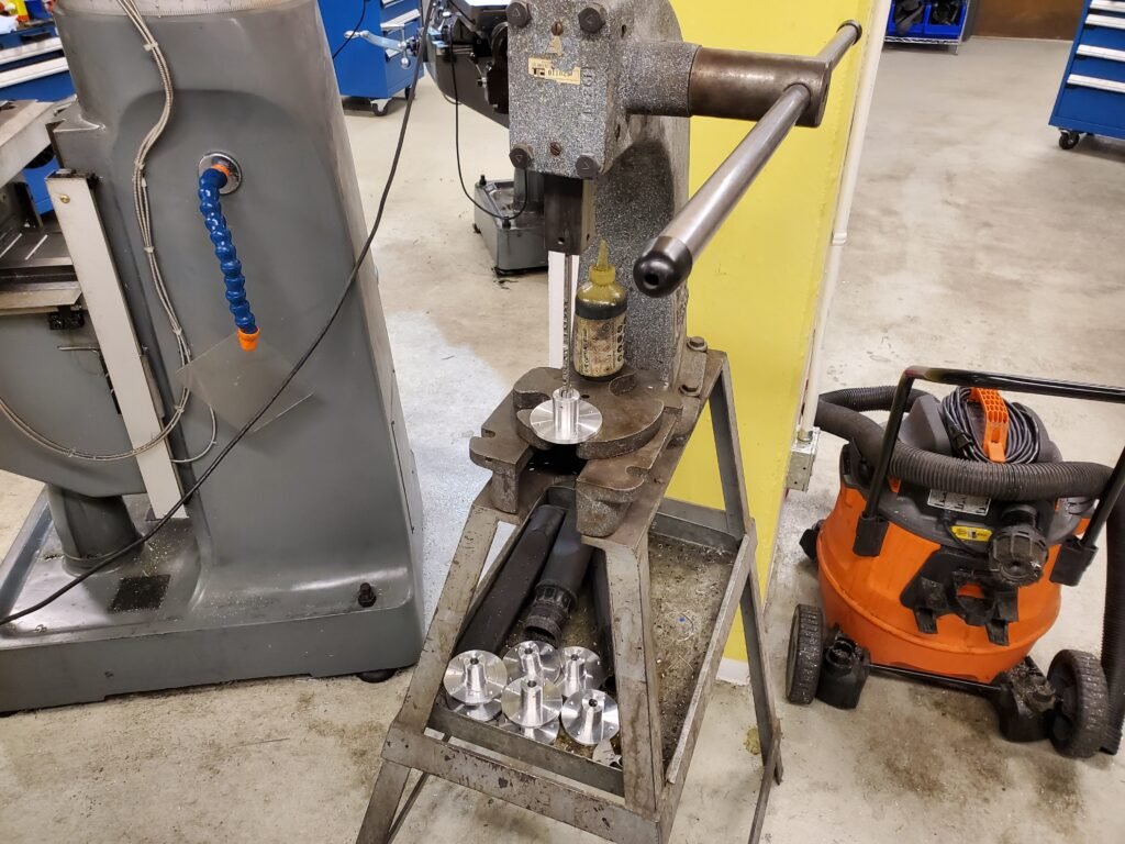
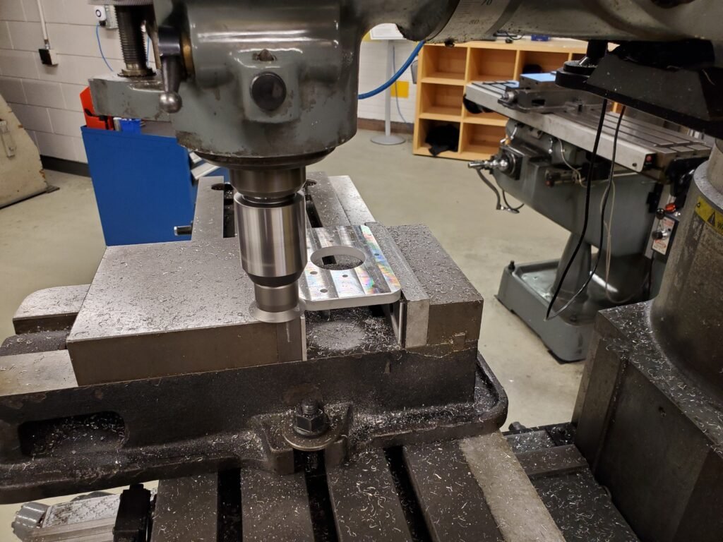
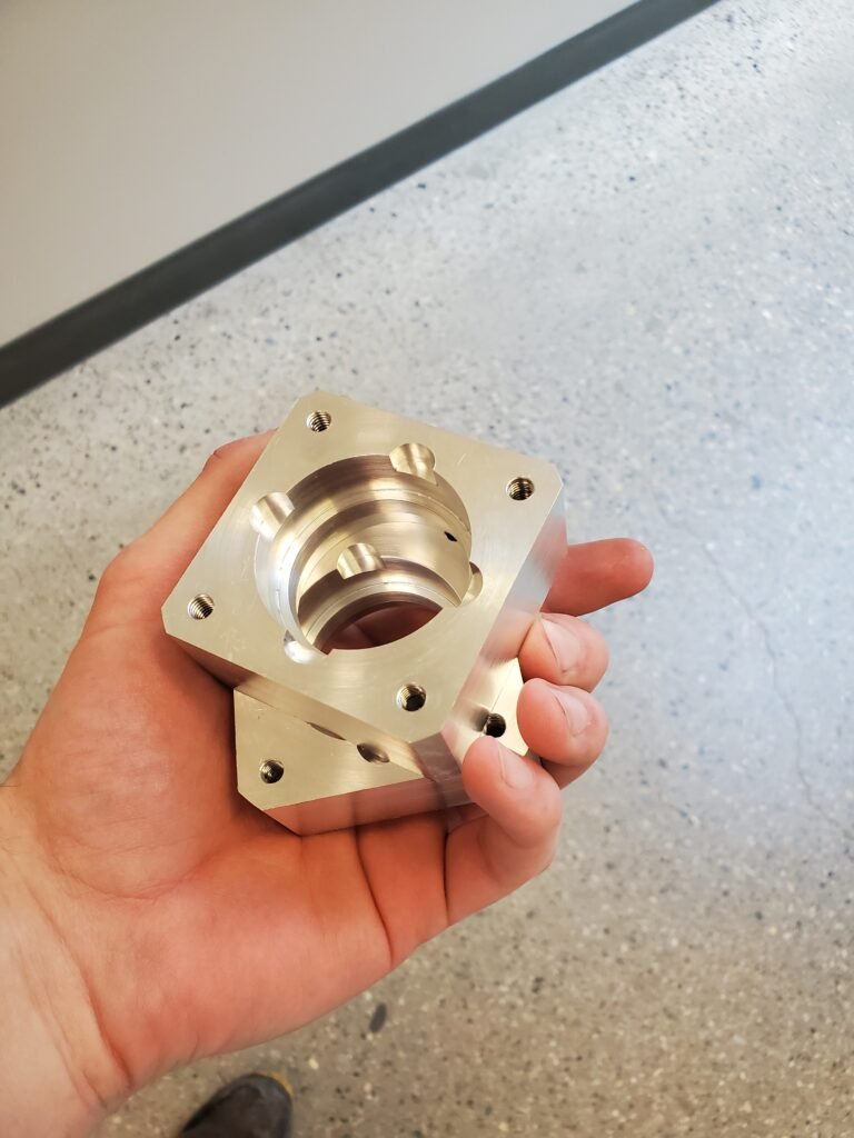
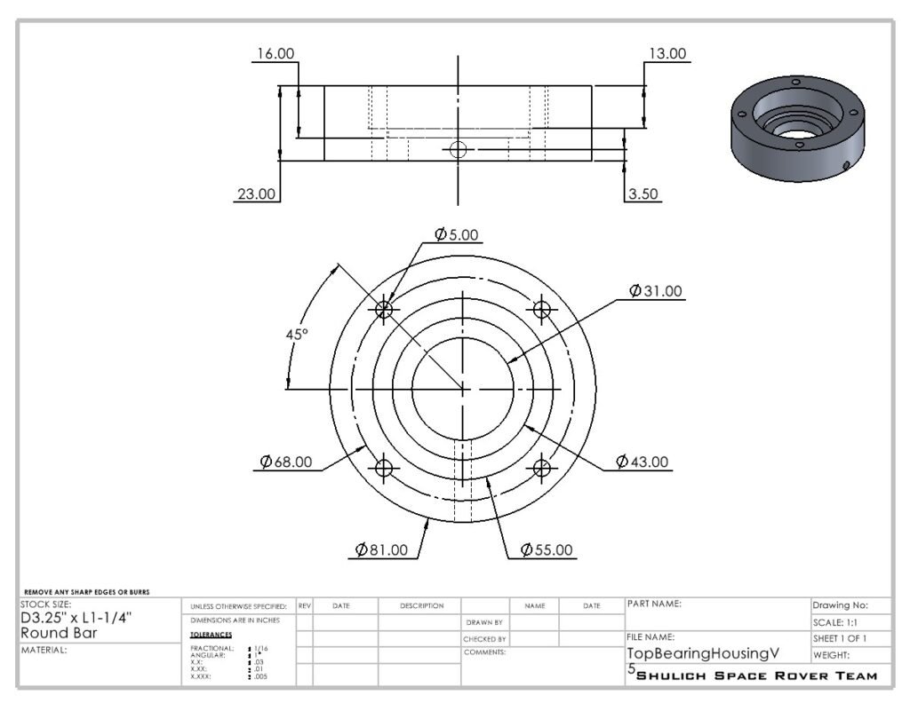
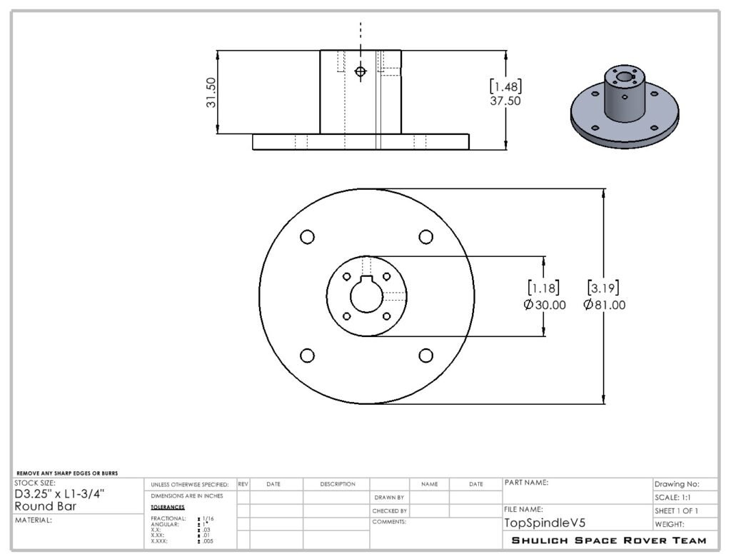
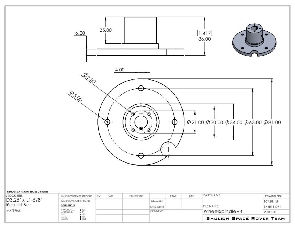
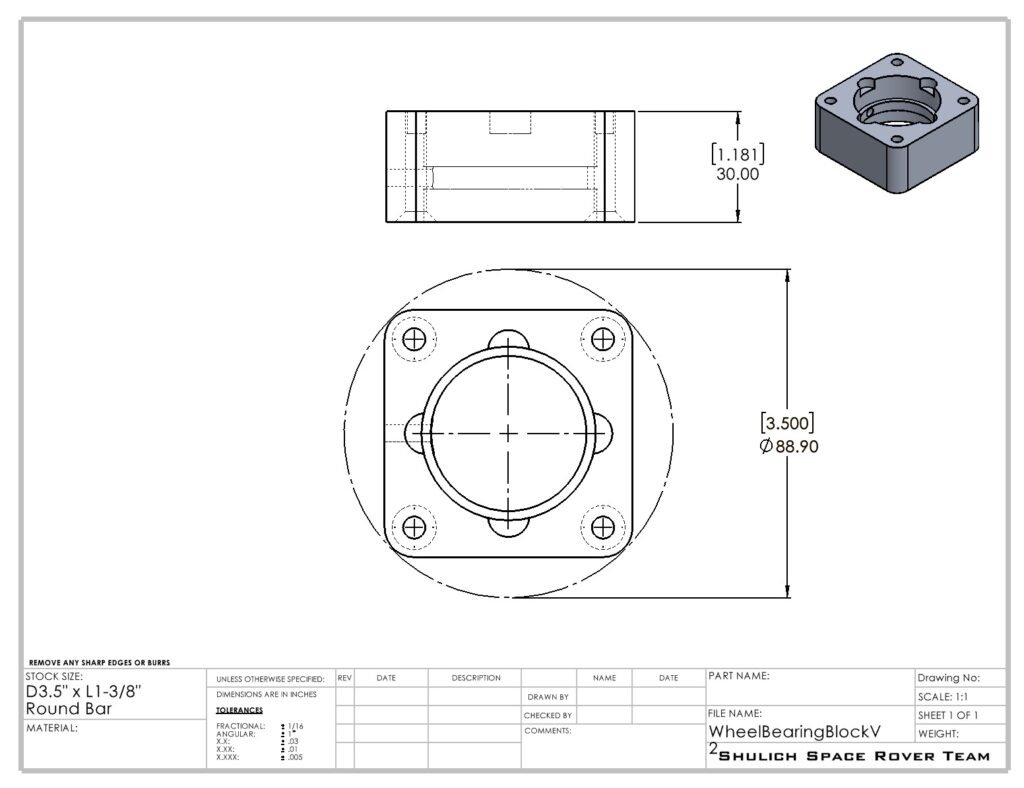
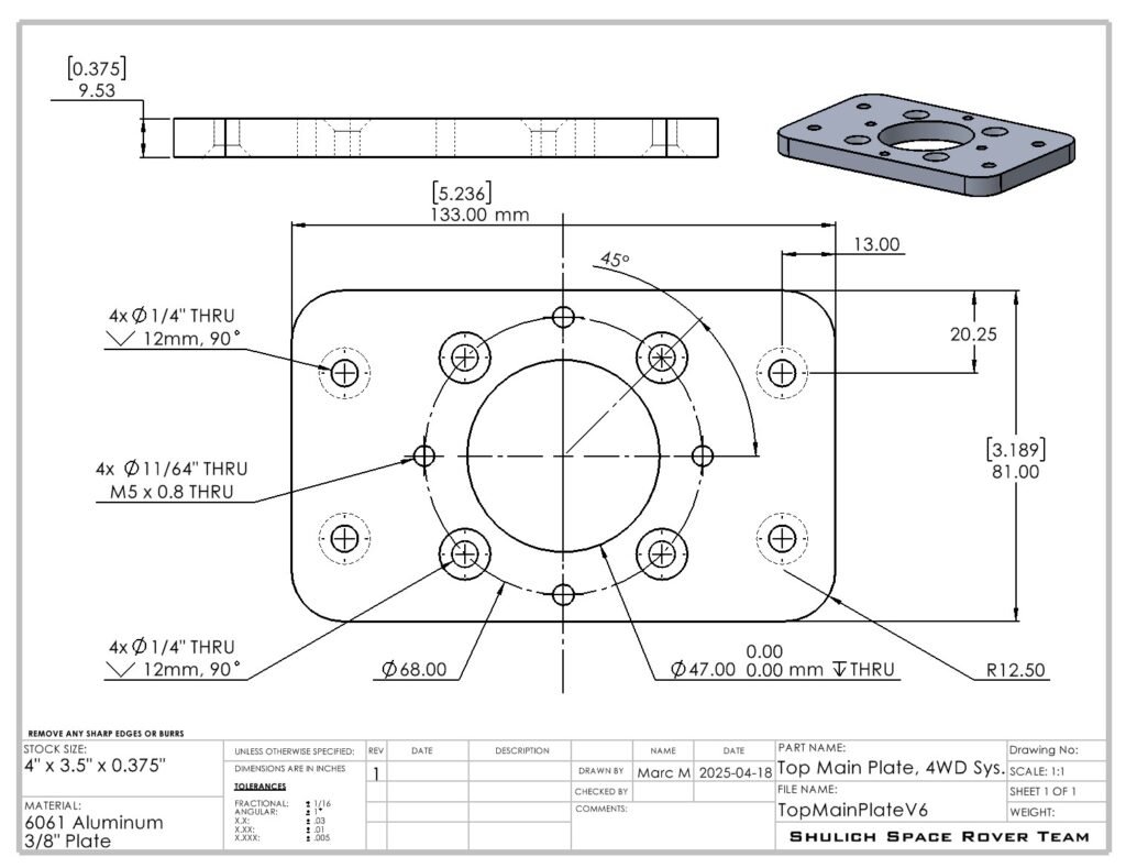
It should be noted that although I had a team of 6 peoples in my sub-division, I was the only one working on this project all year. When it came time to machining, and I had already finished the design, I still couldn’t rely on my teammates to help. The parts shown below were all 100% machined by me, using both my home garage and the machine shop at the university. I’m glad I gained the experience I could from this project, because it costed me a lot of work. It’s not like I hogged the project, I think I was just the only one committed.
Manufacturing