Inspired by David Malawey and the SCUTLLE robot project. For more information visit scuttlerobot.org
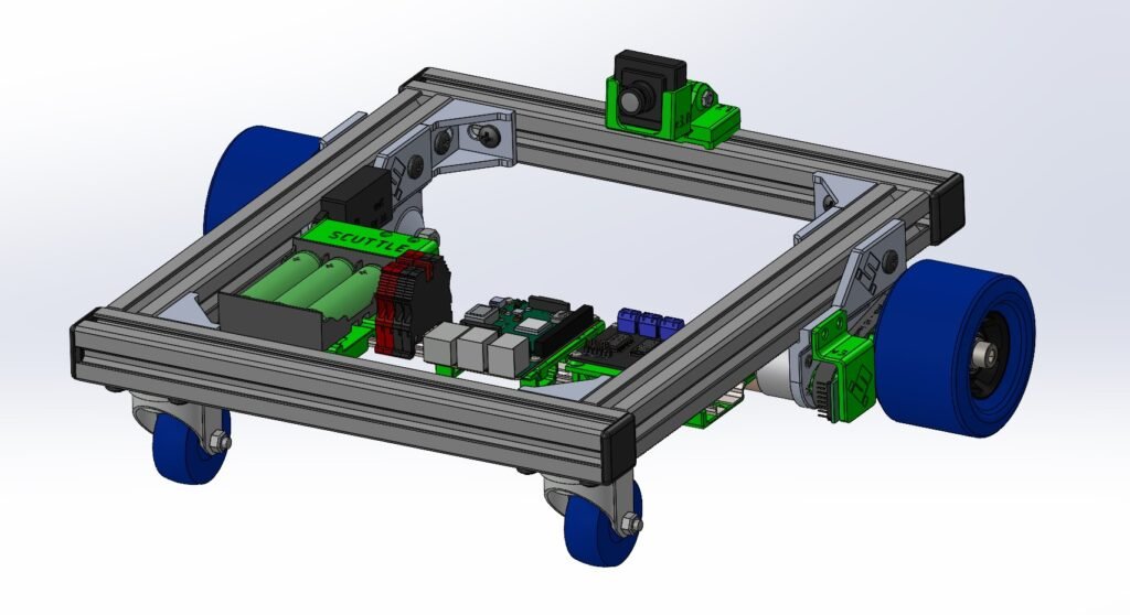
In anticipation of my fourth-year mobile robotics course, I built a version of the SCUTTLE (sensing connected utility transport taxi for level environments) robot to use as a testing platform for the content of the course. I completed the wiring in time, however the course project was replaced by a midterm test instead, and SCUTTLE got shelved.
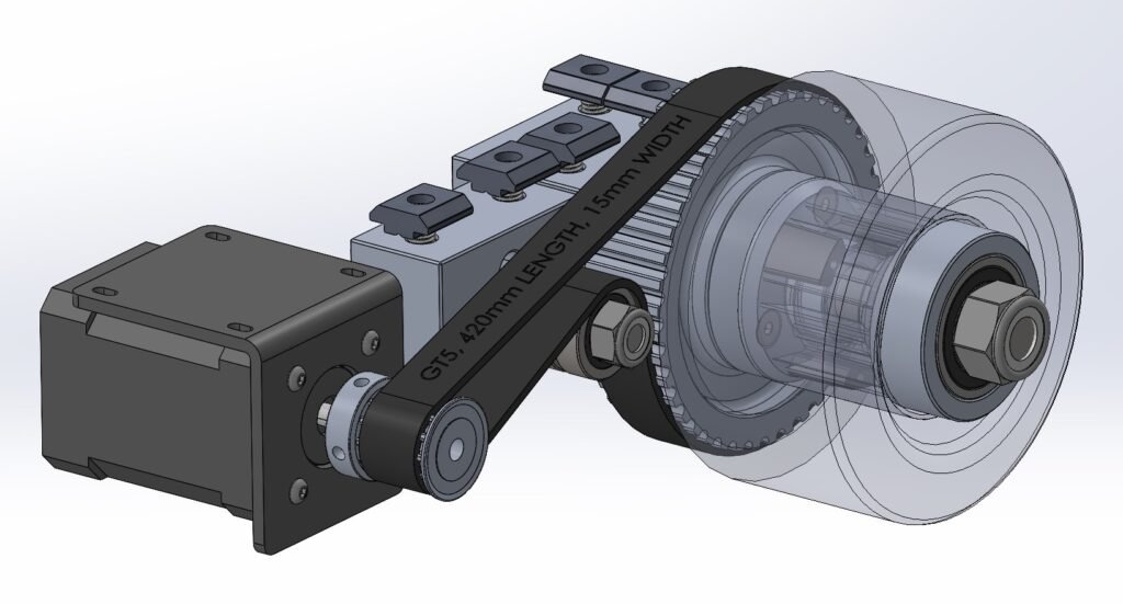
I wanted my SCUTTLE to be unique, and I also feared three things from the original drivetrain design. #1: it lacked a belt tensioner, #2: 708 bearings were riding on a M8 shaft (inevitable ‘play’ in the bearing assembly), #3: geared drive motor allows for backlash of drive wheels, leading to larger uncertainty in pose estimates. Now, I understand that these are minor factors that can be corrected through filtering, but at the time I wanted to build something robust + I wanted to continue my machining spree as I had just finished building the space rover that same summer.
I haven’t completed the software side of this project yet, I anticipate deploying an instance of ROS2 on SCUTTLE and simulating the robot in Gazebo or RViz, once I get the opportunity. This would really solidify my mobile robotics learning with some experiential hands-on application of EKF and motion modelling.
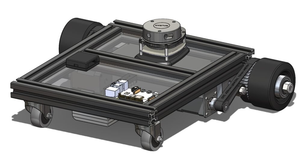
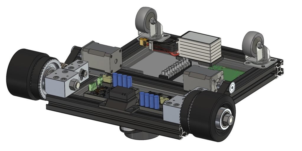
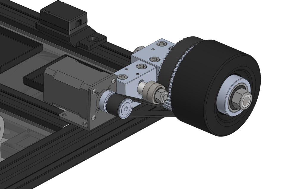
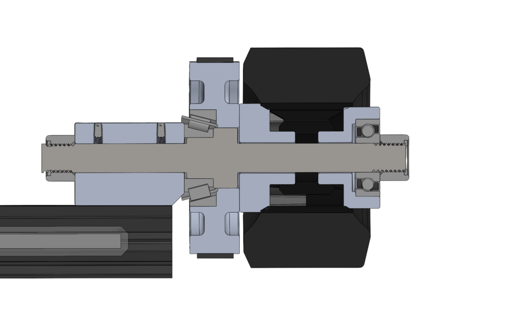
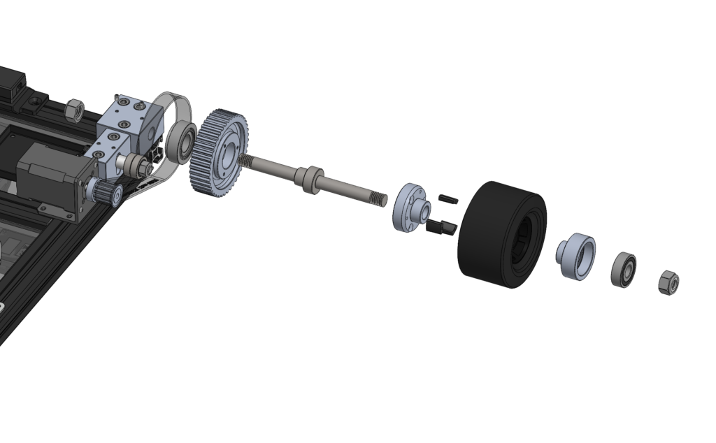
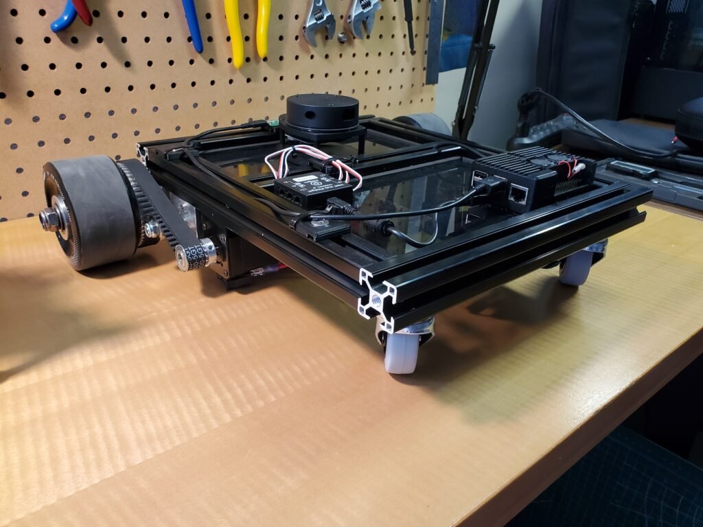
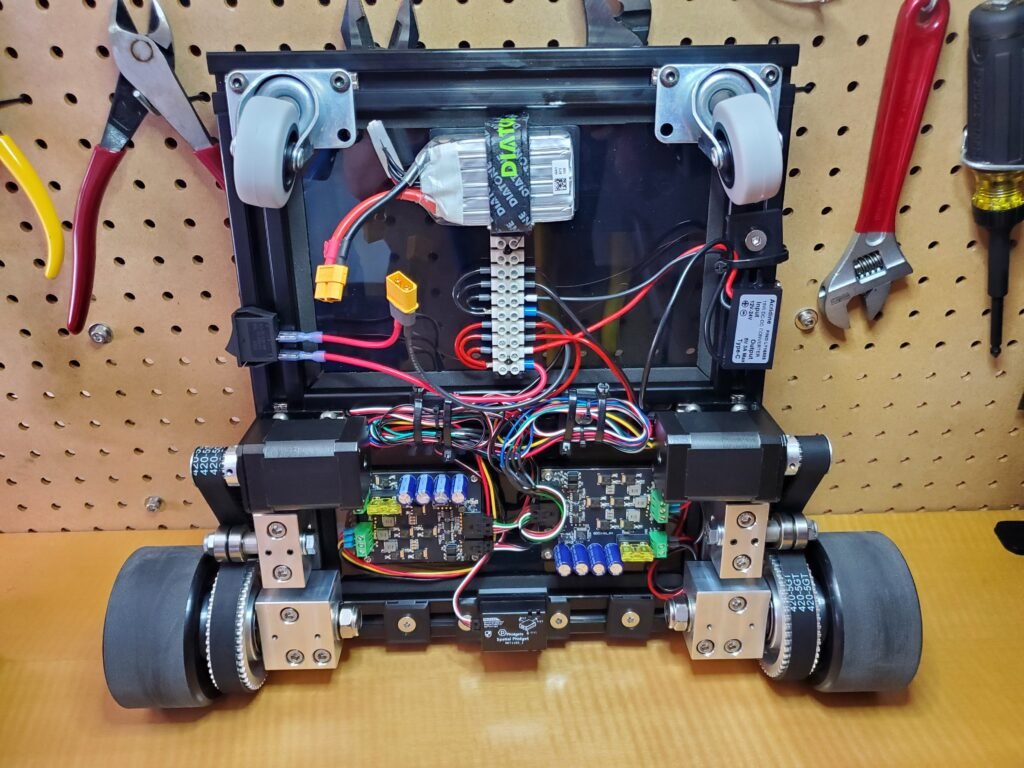
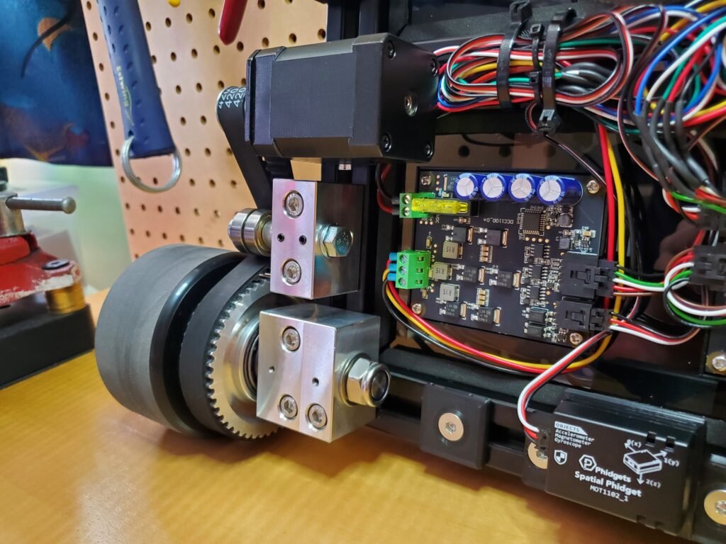
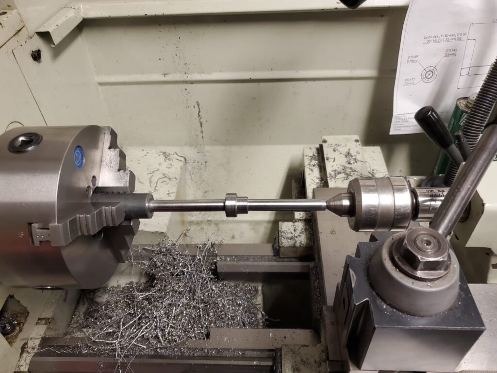
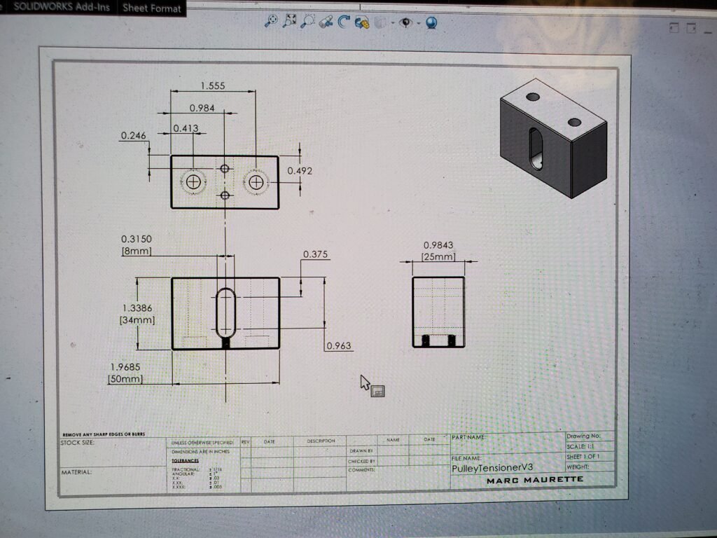
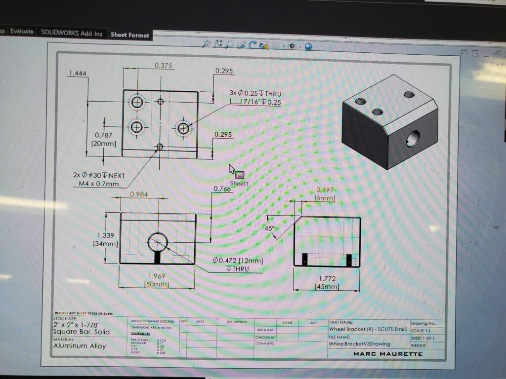
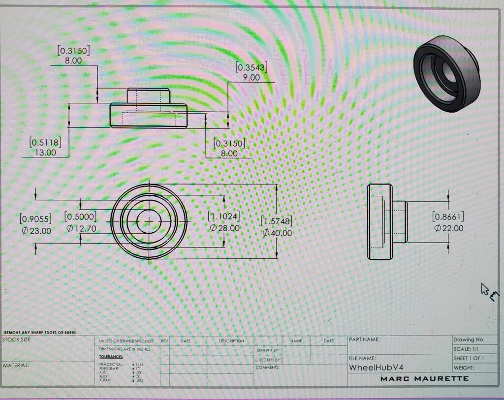
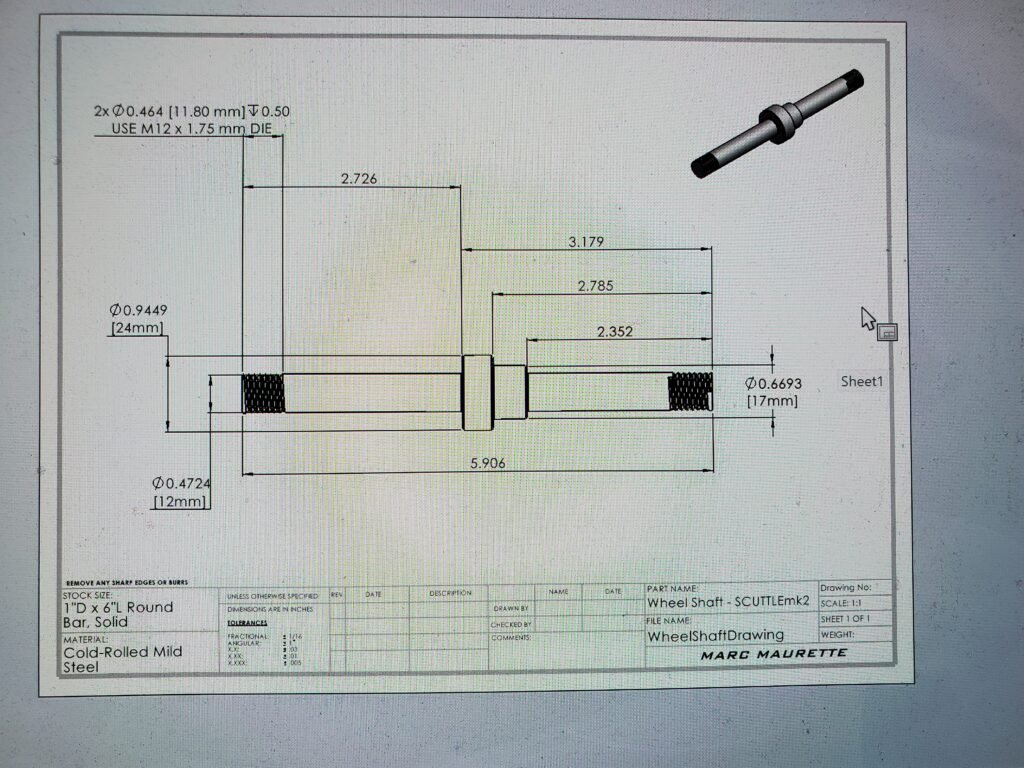
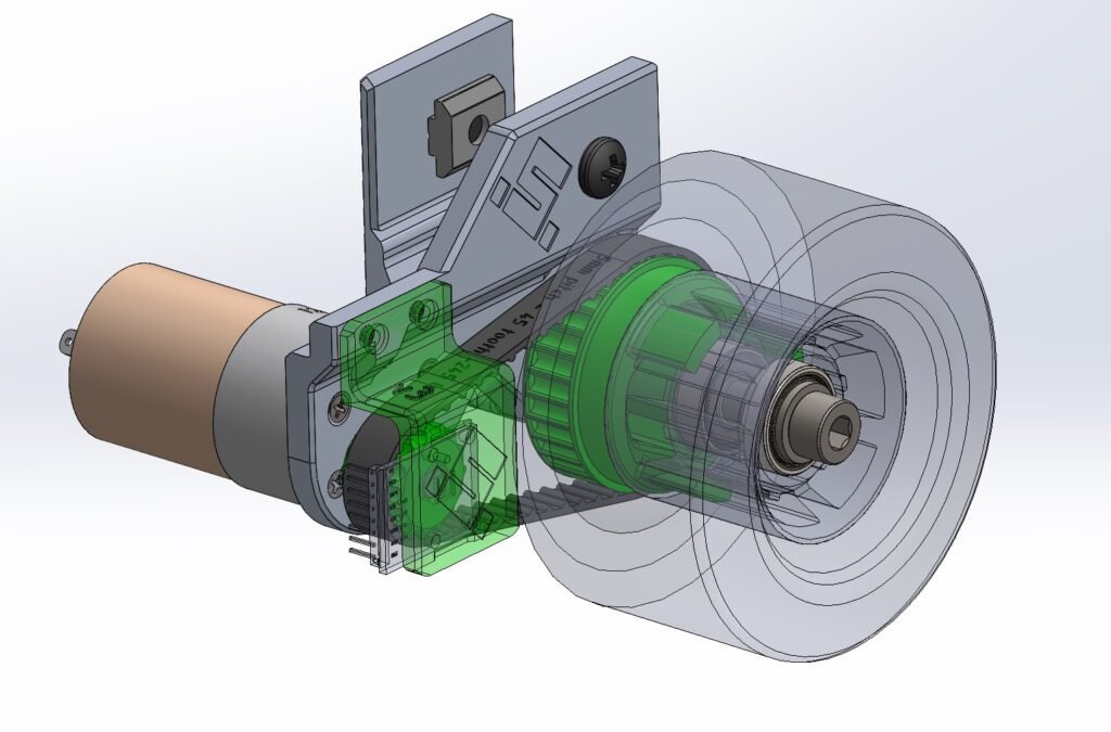
Comparison between original SCUTTLE drivetrain (left) and my redesigned version (right). The original version uses mostly 3D printed parts, as David Malawey advocated that “low skill parts are highly repeatable”, however I wanted to showcase my talent on the mill and machine them out of aluminum. I don’t want to take anything away from the original design though, I still think it’s amazing! and truly genius! I was just looking to try my hand at it, and see what design I would’ve come up with.