Fourth Year University Engineering Project (2025-2026)
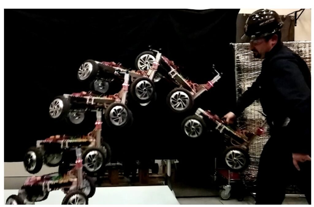
For my capstone project, I applied to work on an improved version of a “throwable robot”, where the robot would be capable of correcting it’s aerial attitude in mid-air using the reaction torque of its drive wheels to land level – like a cat. This project was previously attempted by another capstone team 3 years prior, but failed to meet the project requirements. I chose to apply for this project because it seemed like a good challenge, and was right up my alley in mechanical design and mechatronics systems integration.
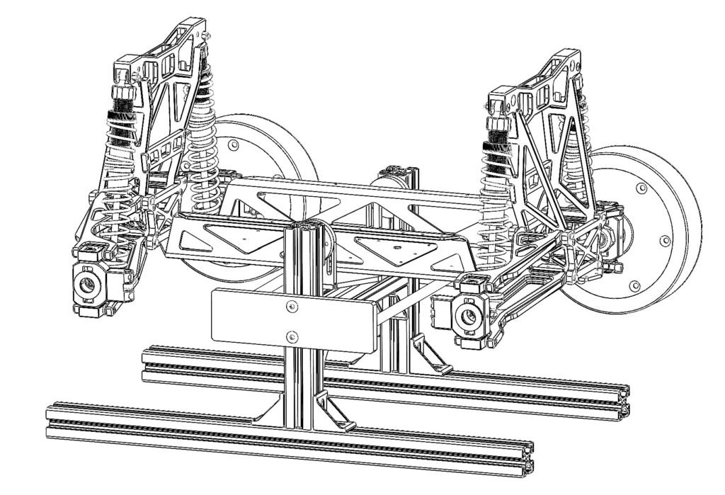
The sponsor for this project was the robotics lab located at the university, so the final design also included a testing stand for further laboratory research and testing. I can’t emphasize enough how great of an opportunity this project was to work on for me. It seemed as though everything I was learning in my fourth year (which I had prepared to apply elsewhere on my other projects) was right-on-time applicable to this project, and that became my sole focus at times. I’ll appreciate it that much for keeping my busy XD.
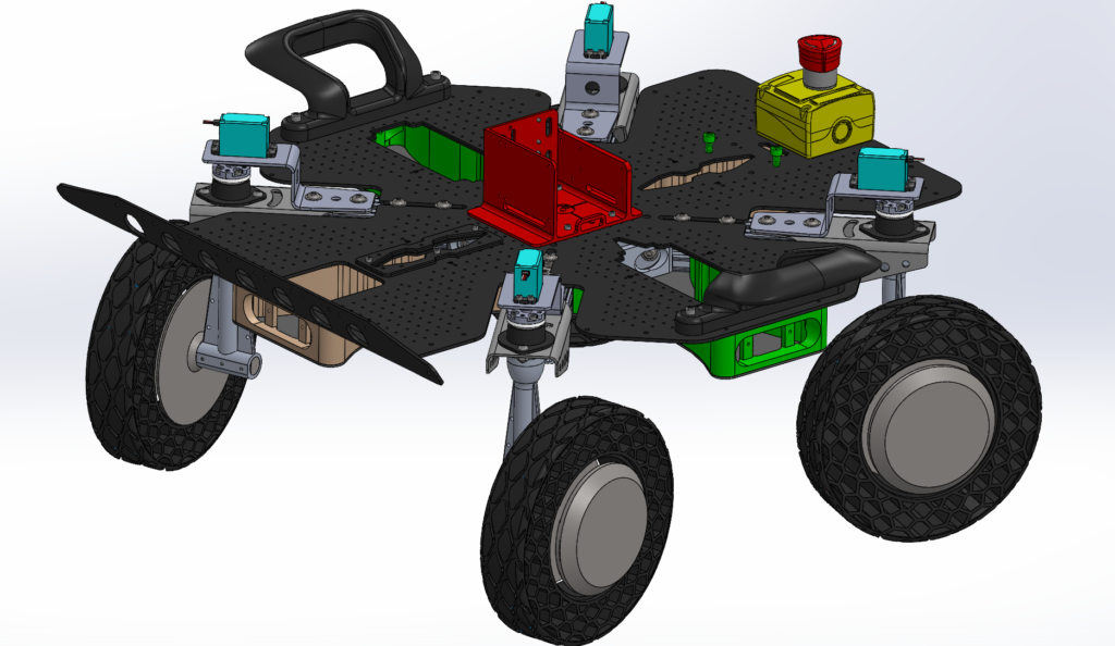
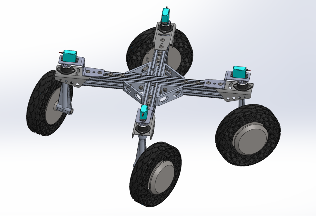
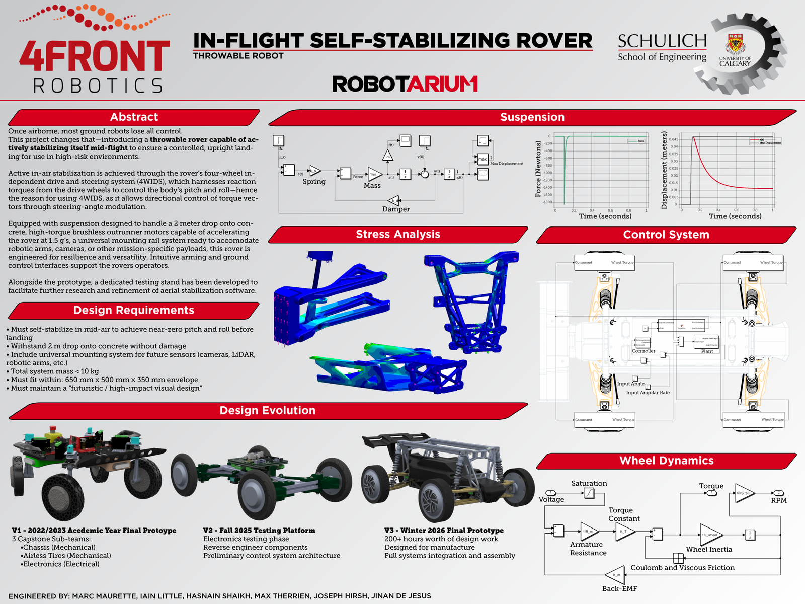
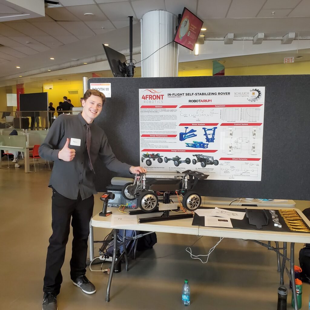
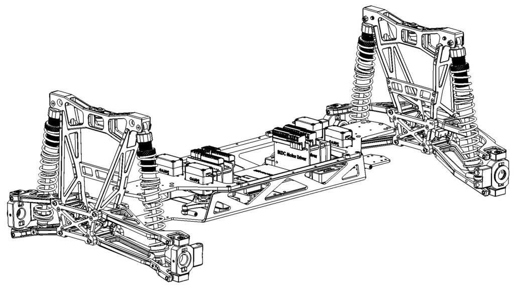
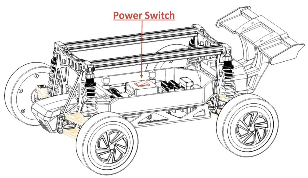
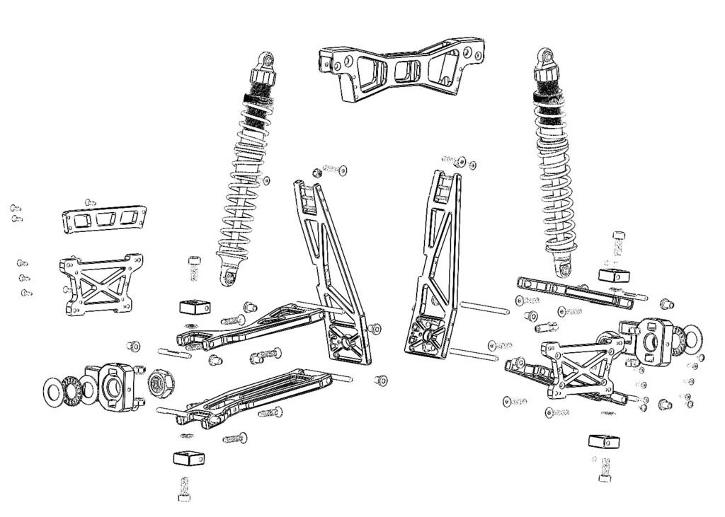
So what did we do? I’m hoping my poster can explain most of that. I’ll include screenshots and captions of my work, but this was a very involved and challenging project which took the entire course of two semesters to complete so it’s hard to know where to start explaining. The evidence of the process is shown below.
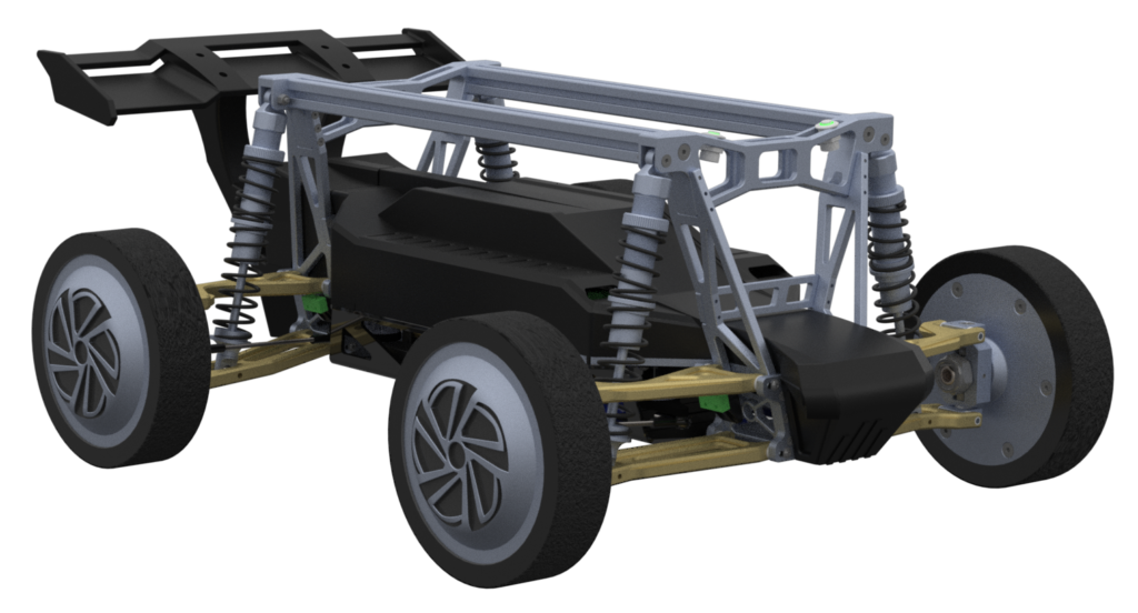
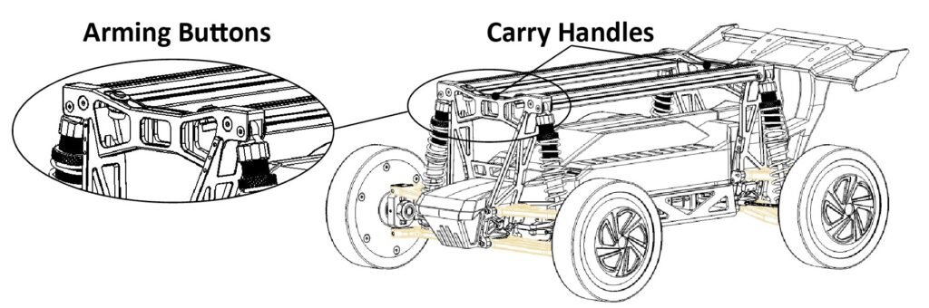
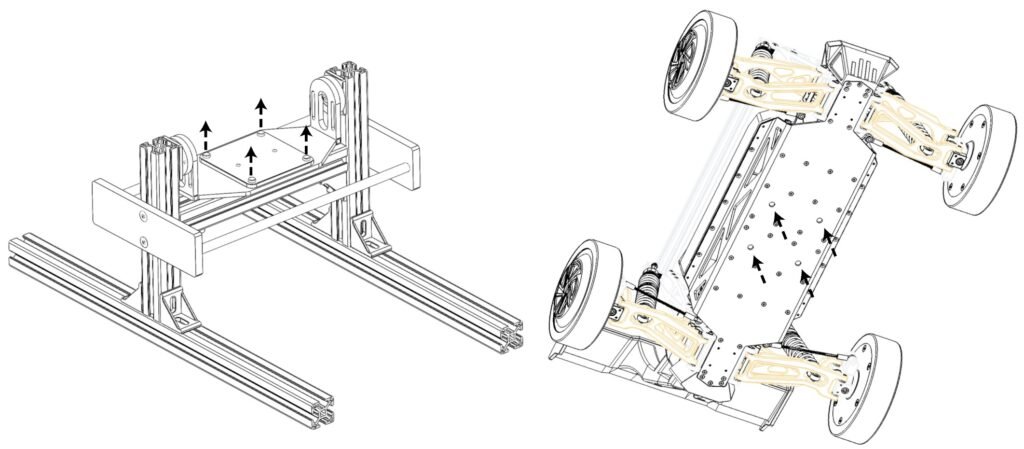
Instructions Manual Images:
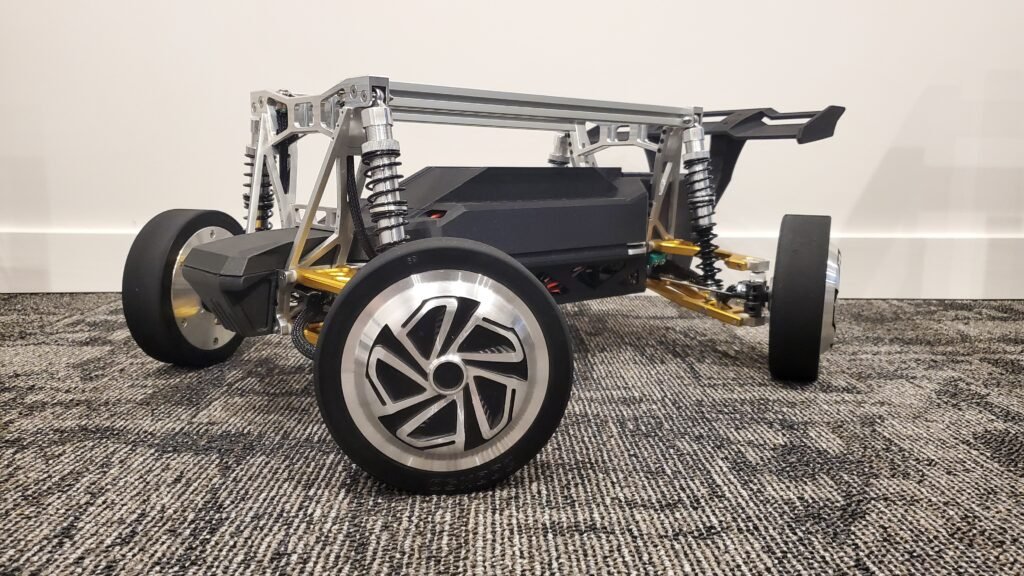
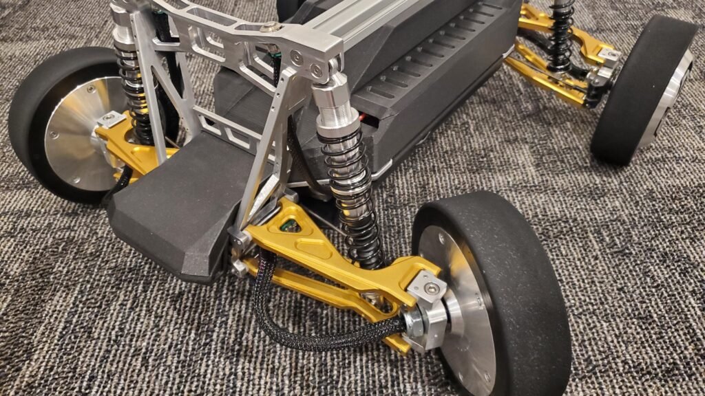
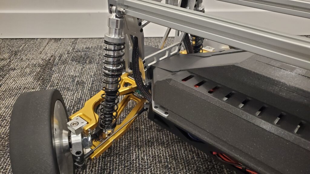
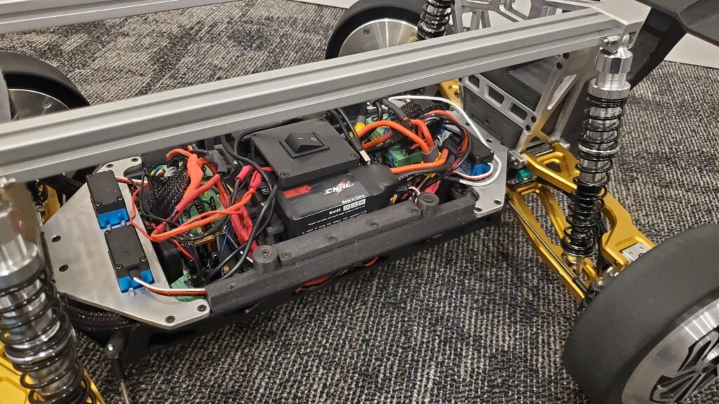
Finished Prototype Gallery:
Suspension design Evolution:
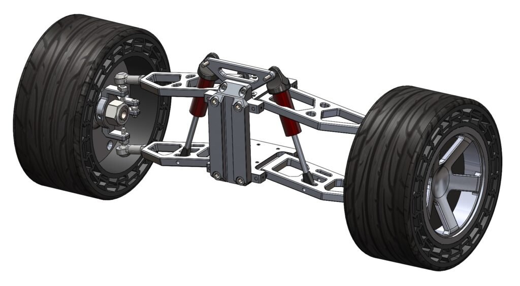
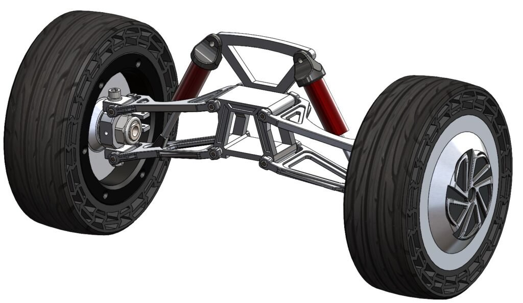
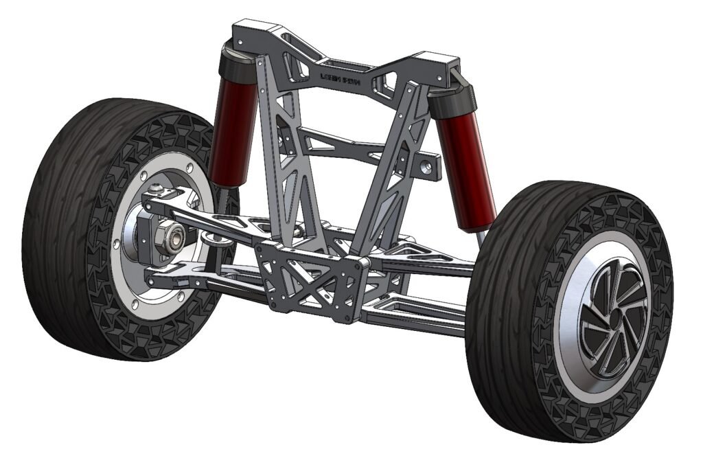
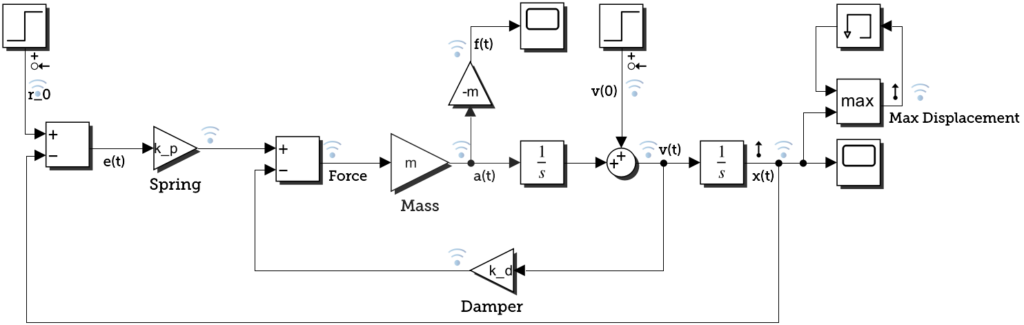
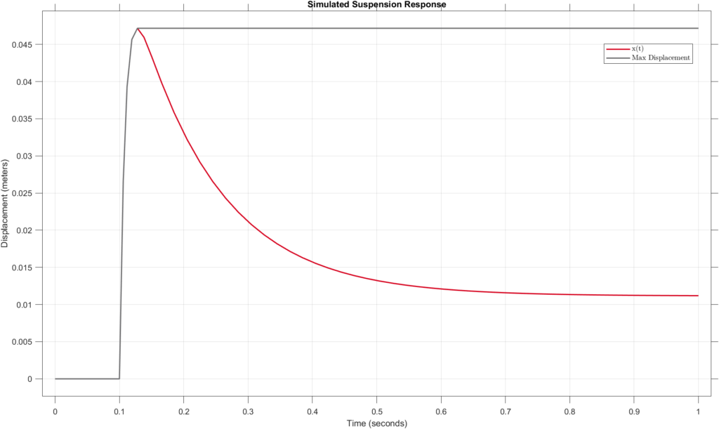
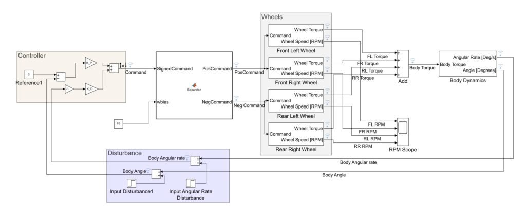
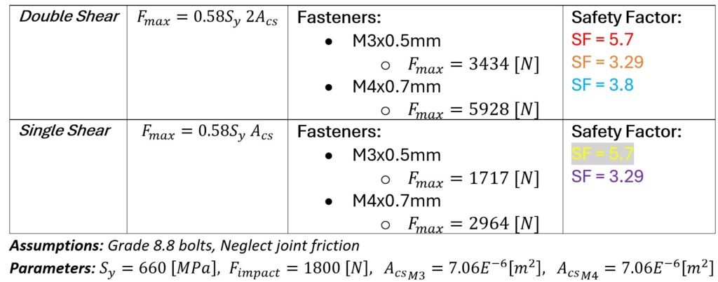
Bolted / Pinned Joints Stress Analysis:
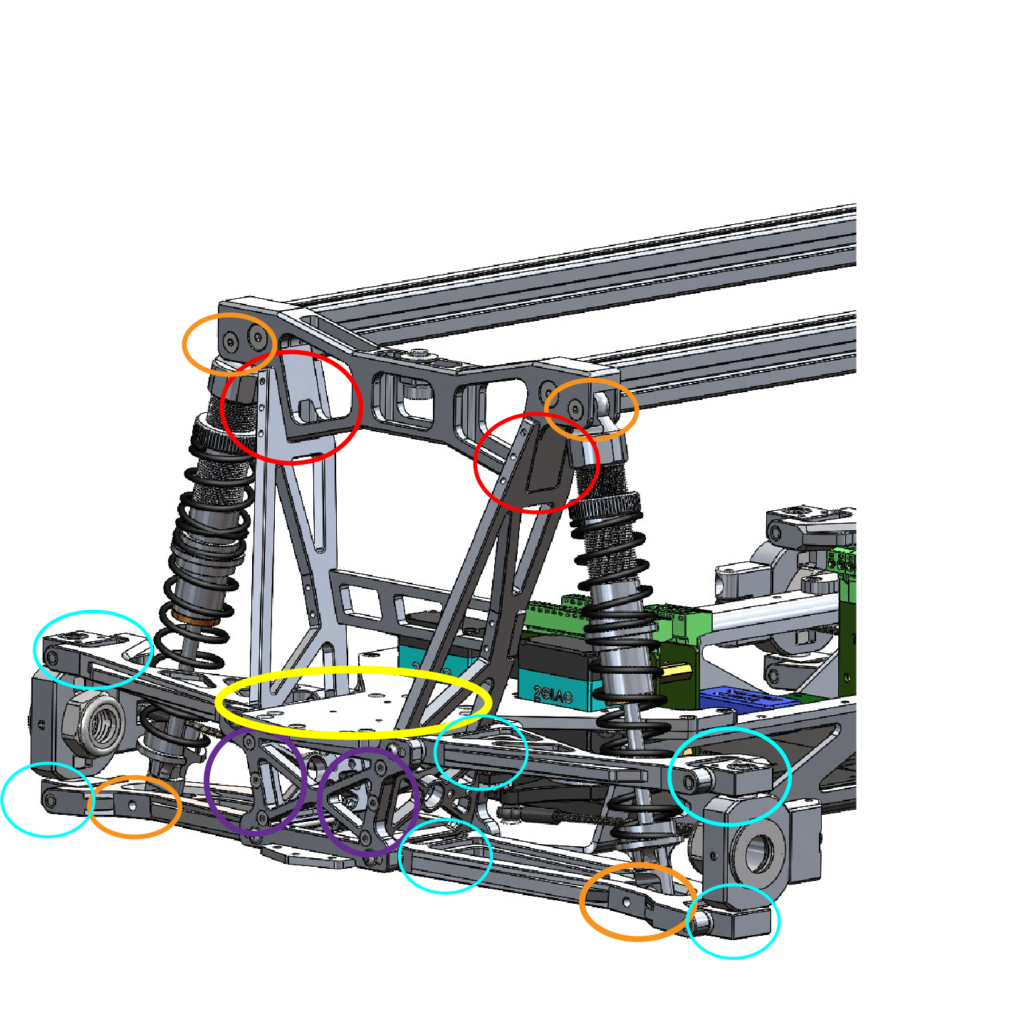
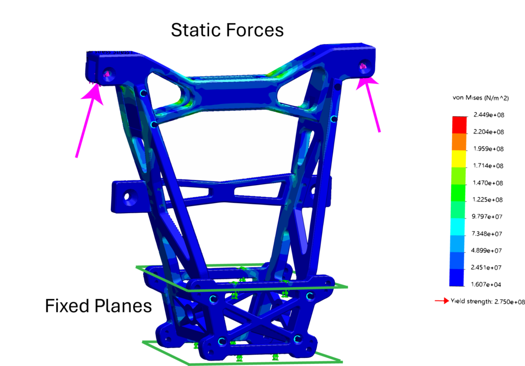
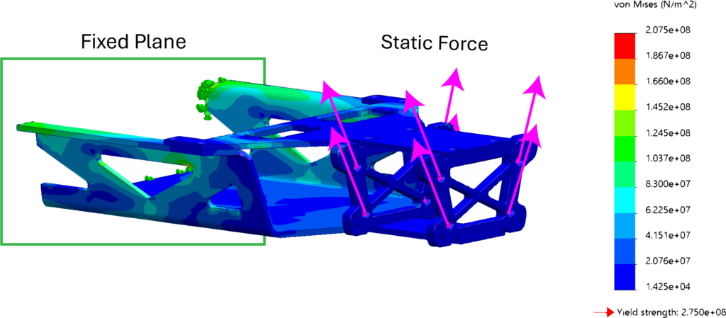
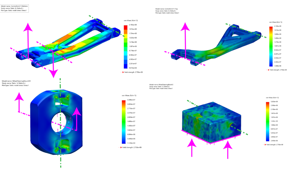
FEA Stress Analysis:
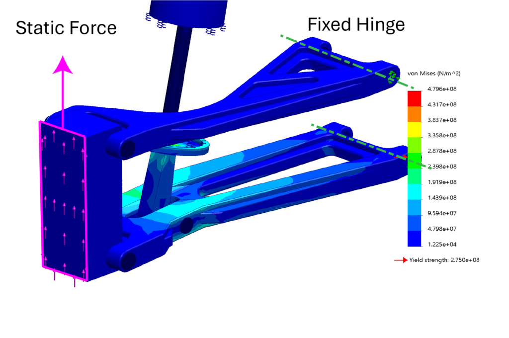
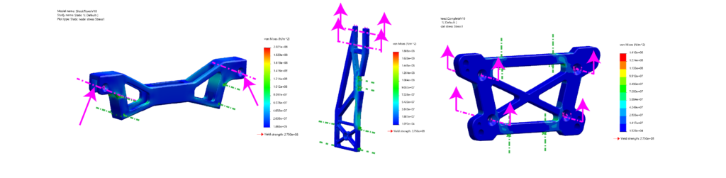
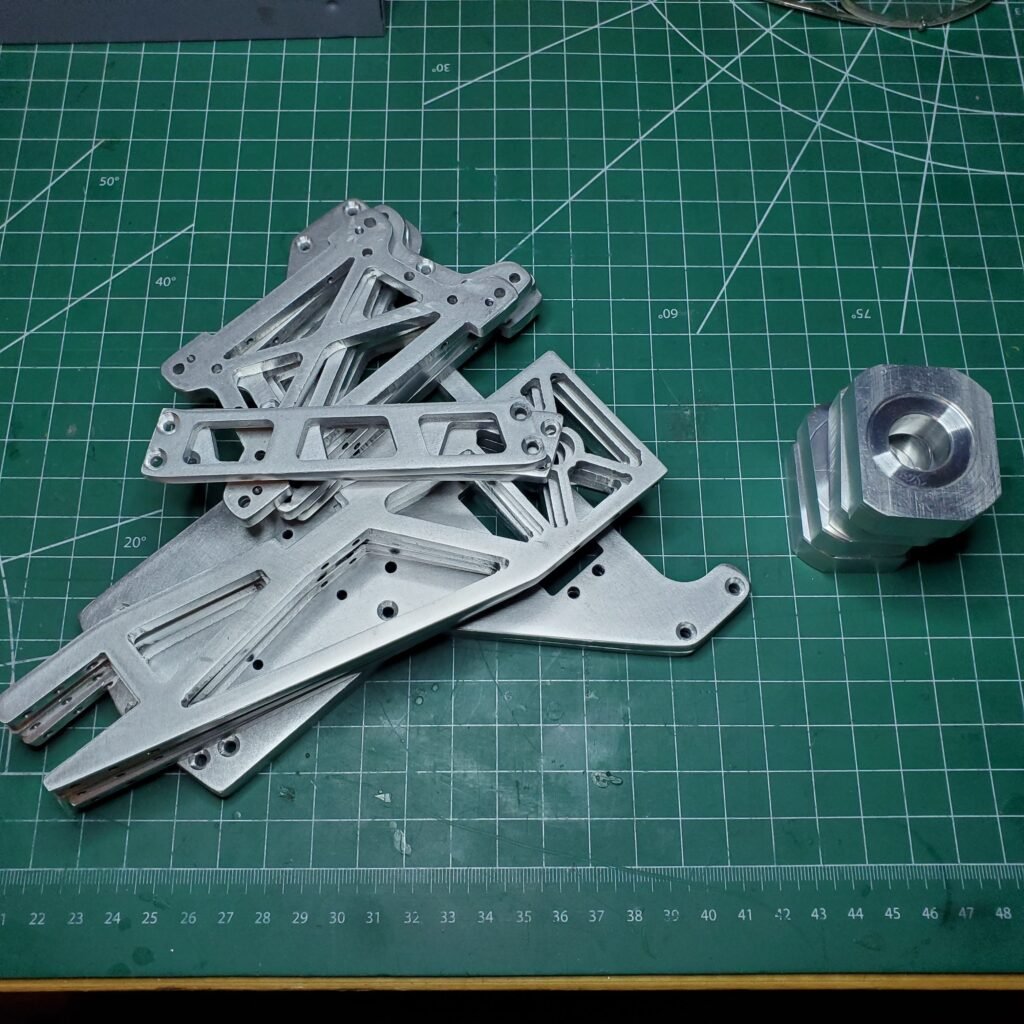
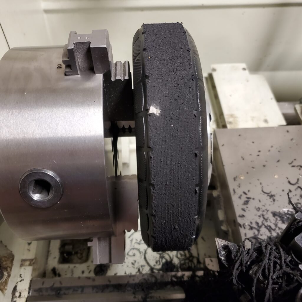
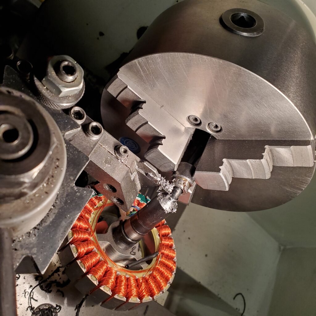
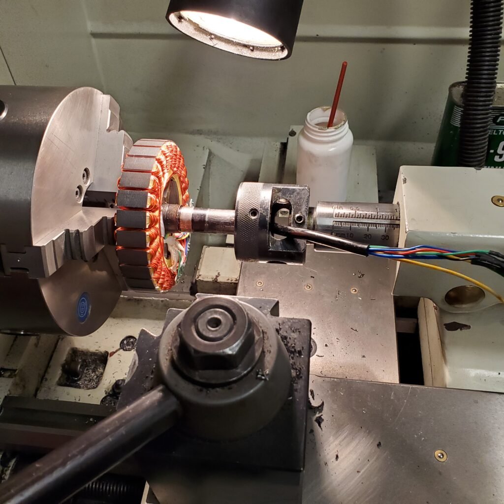
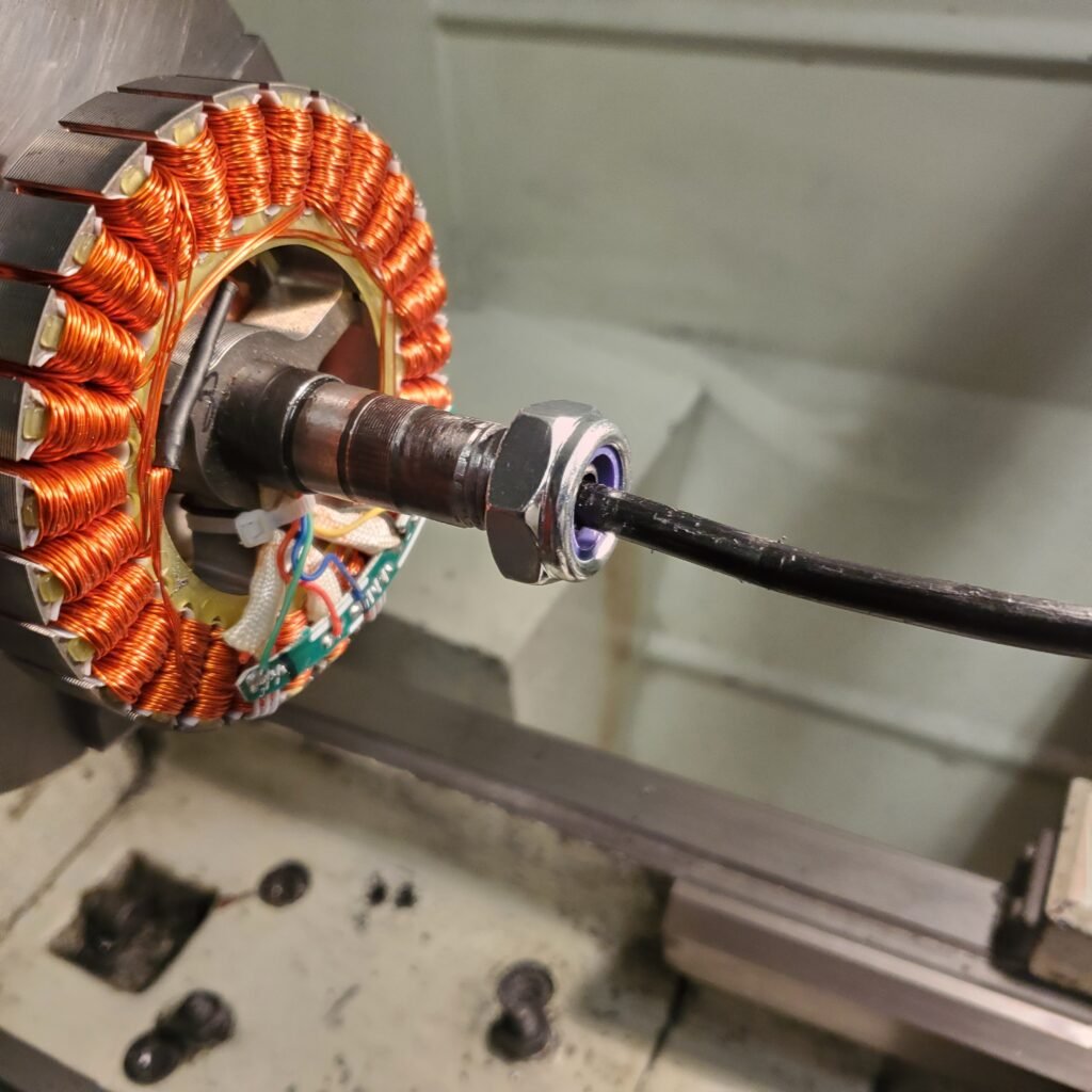
Manufacturing:
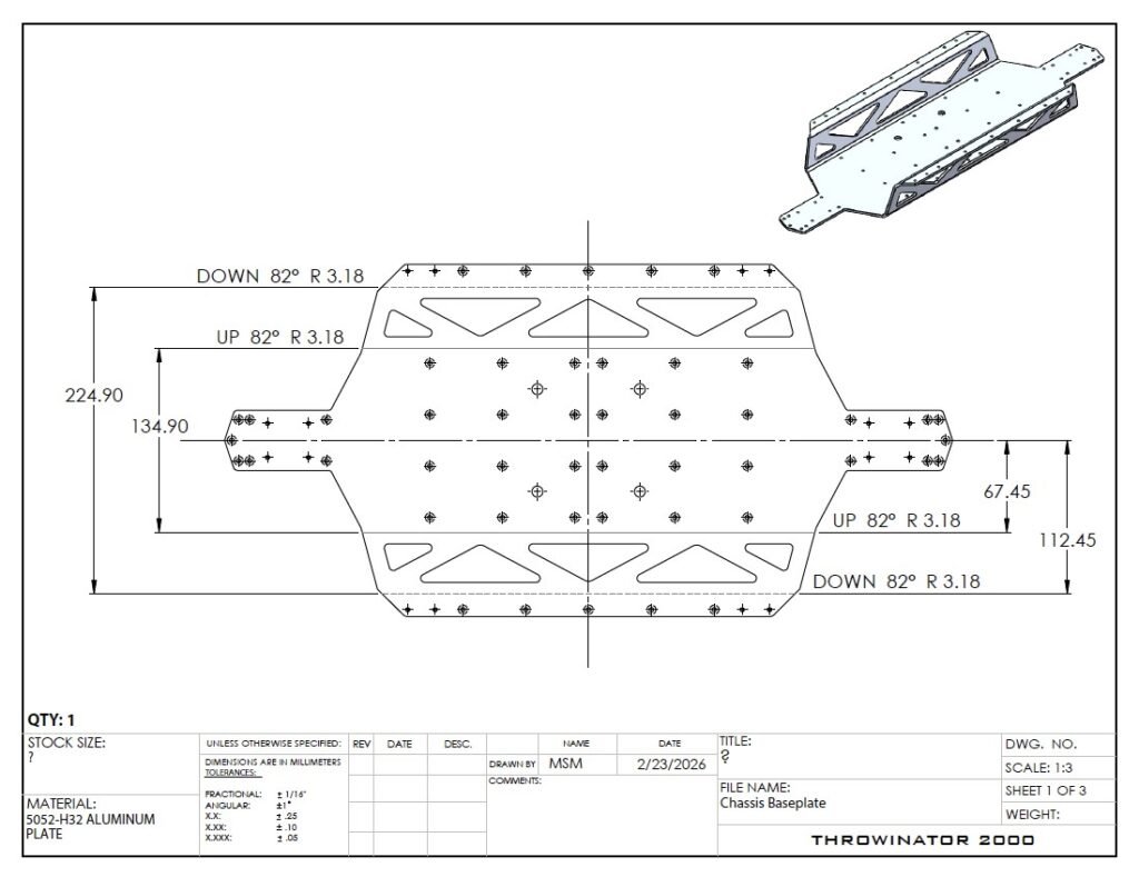
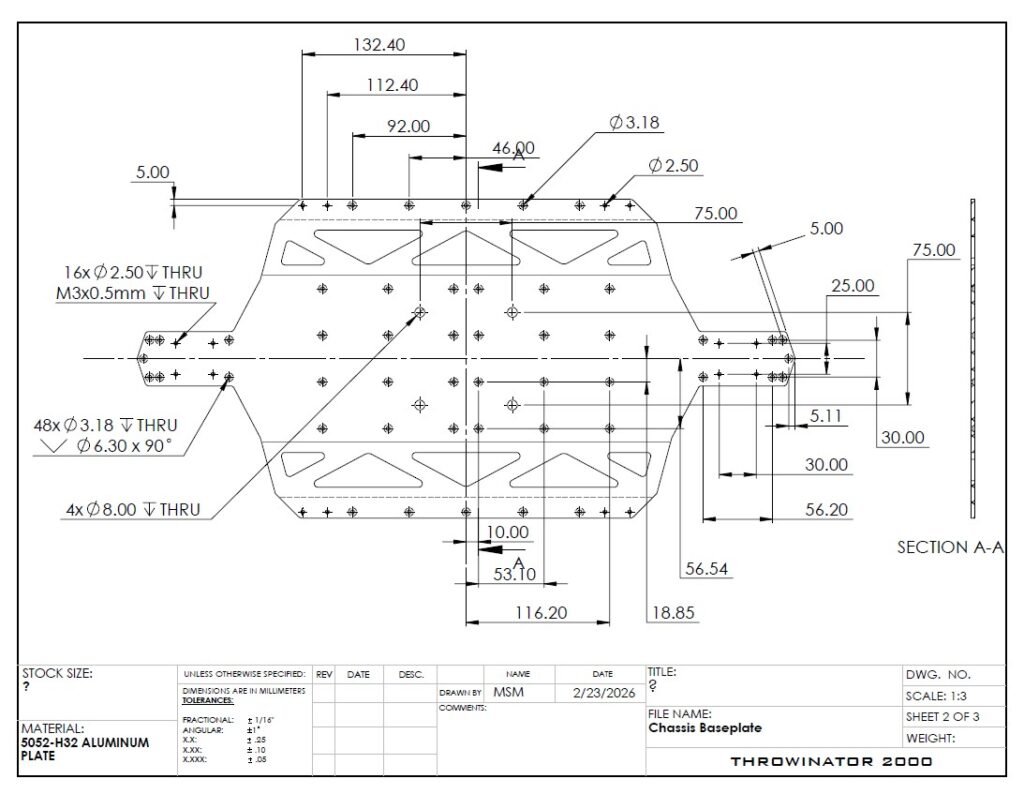
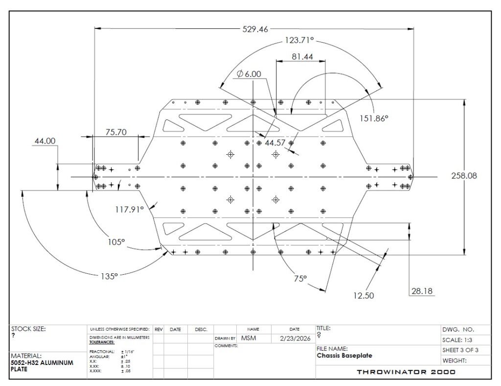
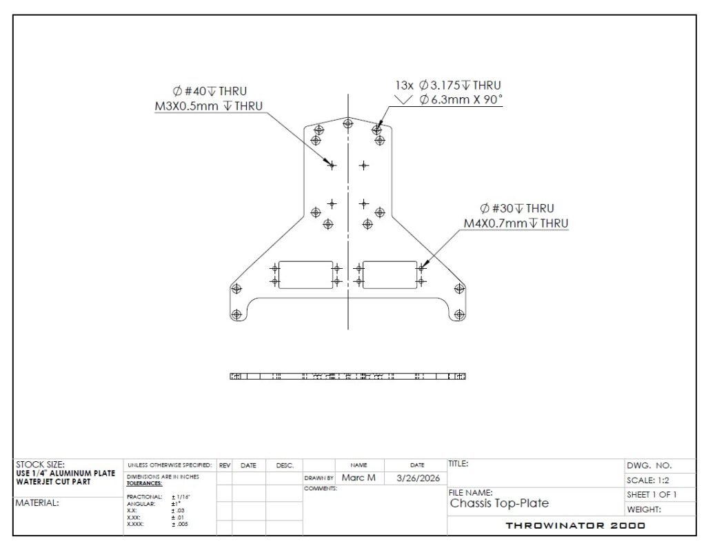
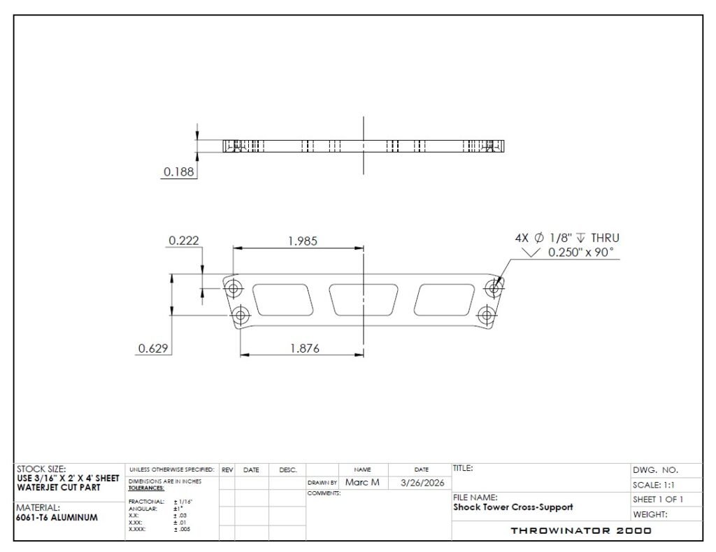
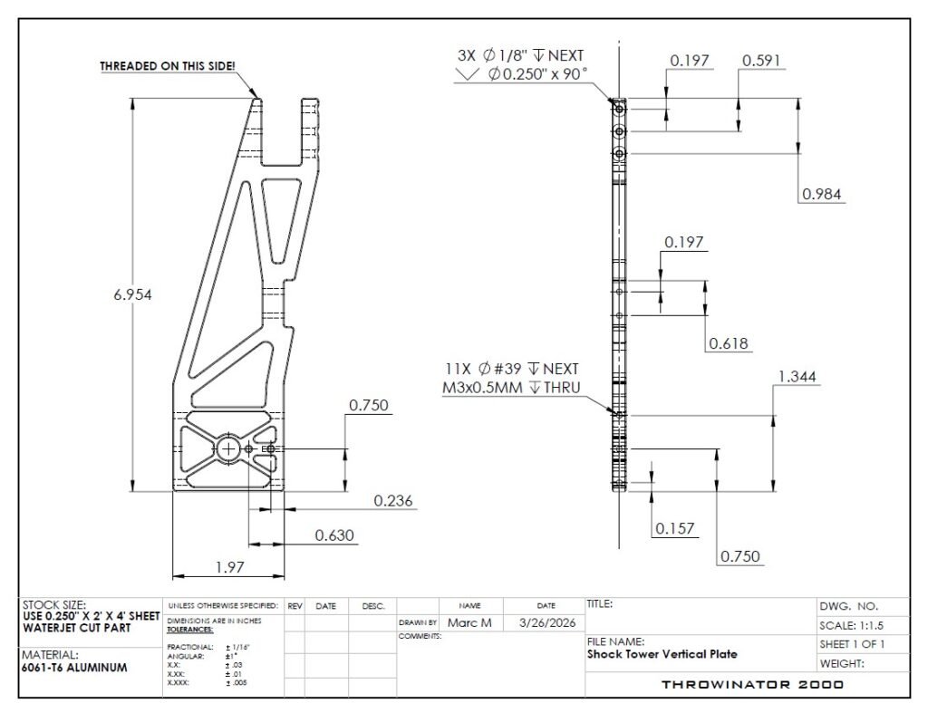
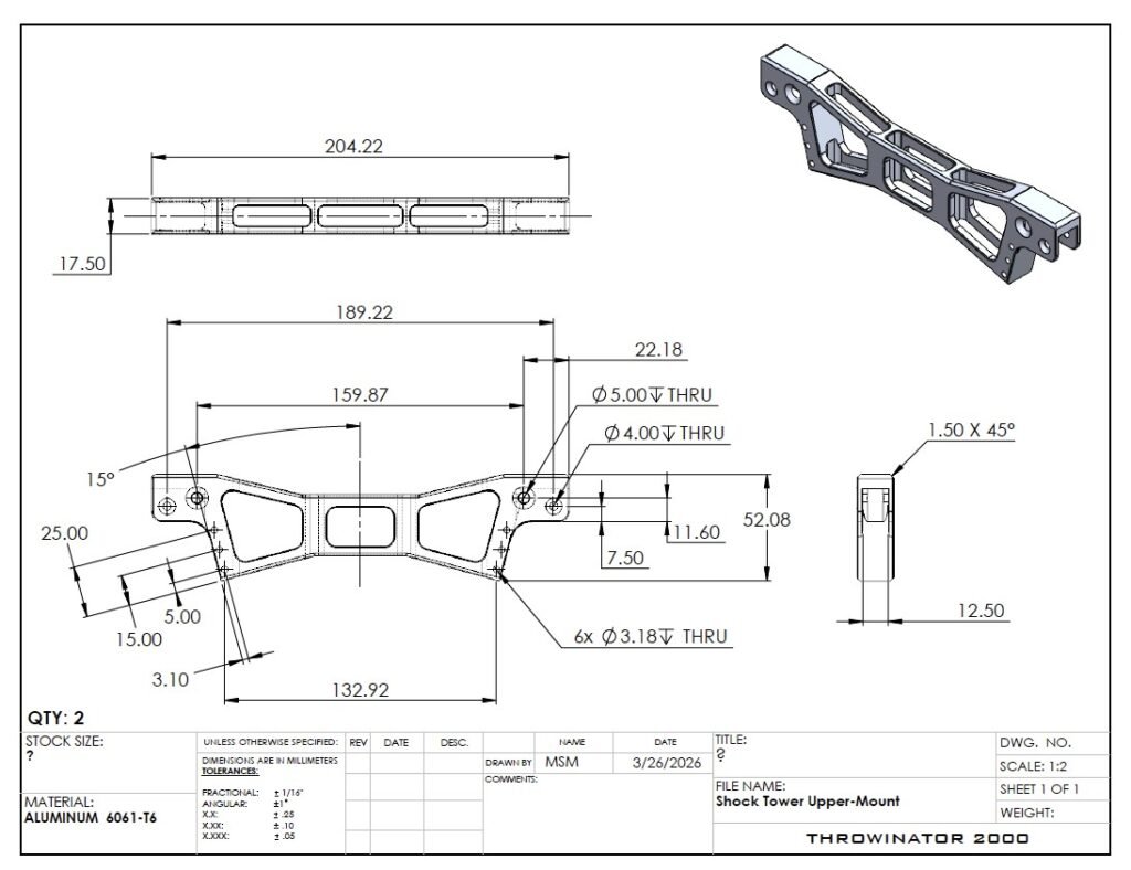
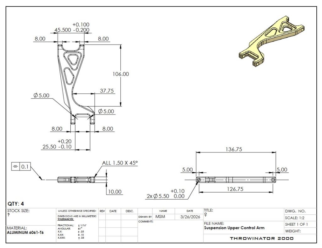
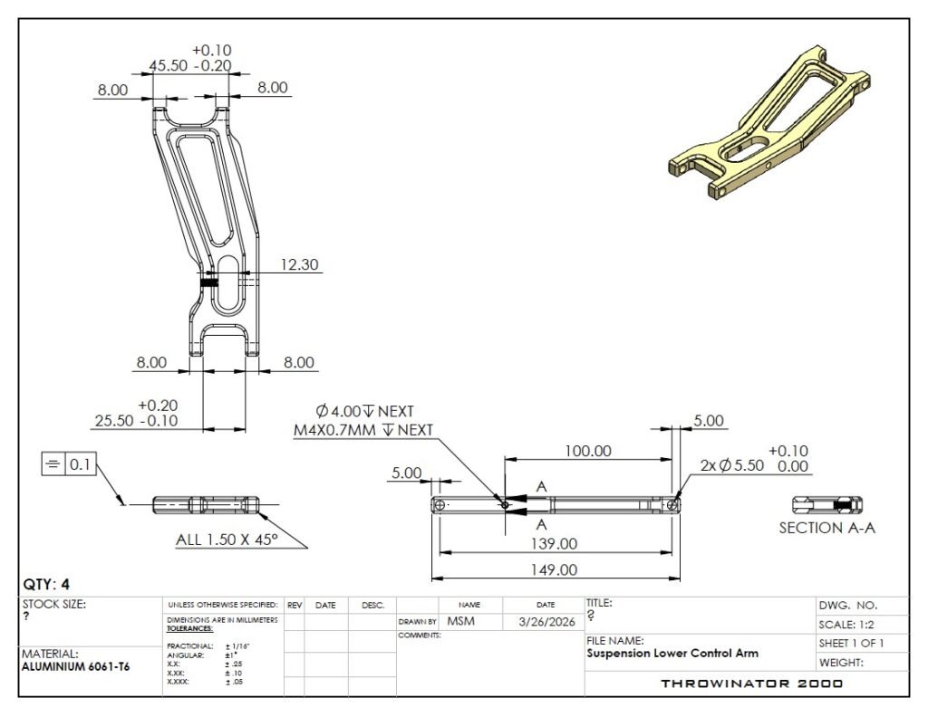
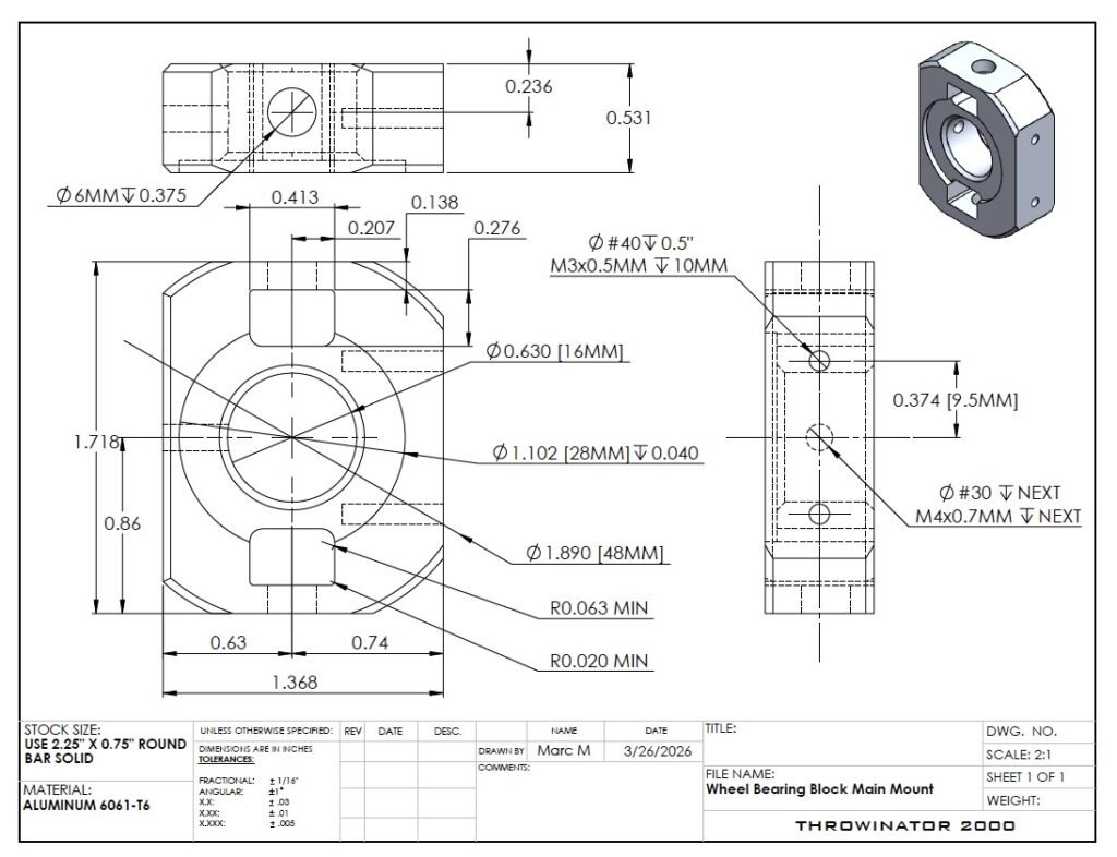
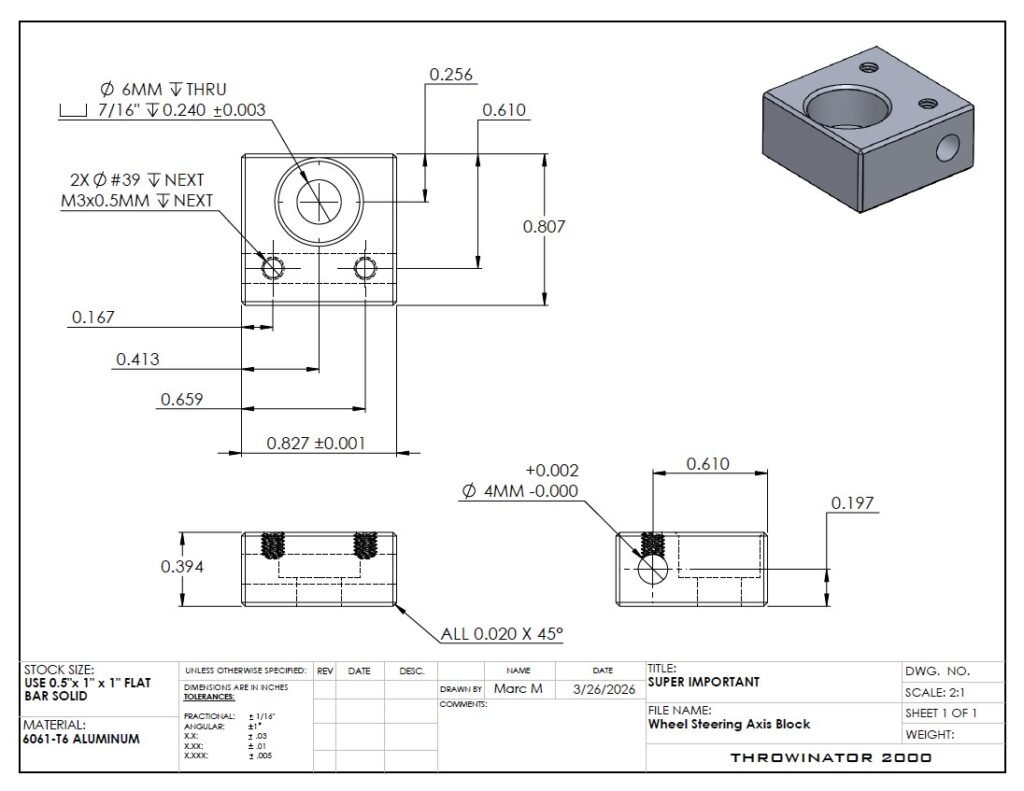
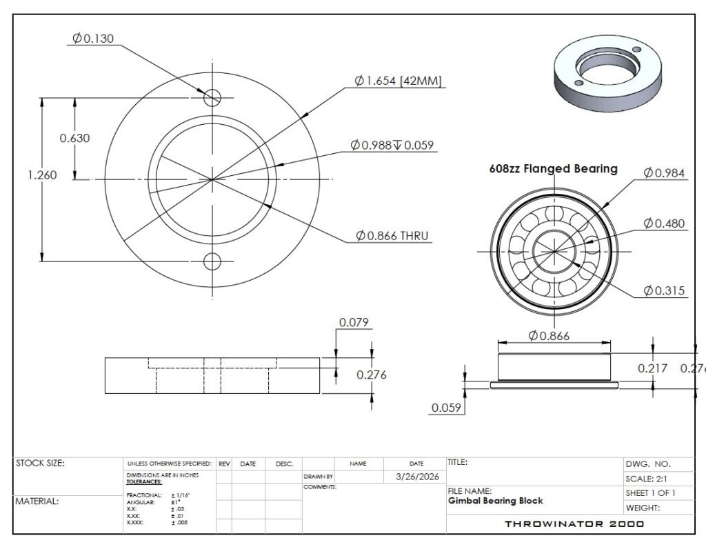
Technical Drawings:
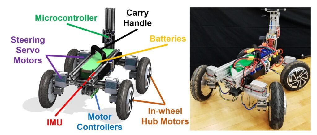
Prior Art:
Below is the rover design the previous team who attempted this project produced. Subsequently, we had to salvage as many parts as possible from this rover and use them in our build.